
Capacitance Multiplier and Loop Filter Noise Reduction in a PLL

a capacitor multiplier and loop filter technology, applied in the field of phase locked loops, can solve the problems of large device size, electrical noise, thermal noise, etc., and achieve the effect of reducing the thermal noise of the second

Active Publication Date: 2016-01-07
STMICROELECTRONICS INT NV
View PDF5 Cites 11 Cited by
  • Summary
  • Abstract
  • Description
  • Claims
  • Application Information

AI Technical Summary

Benefits of technology

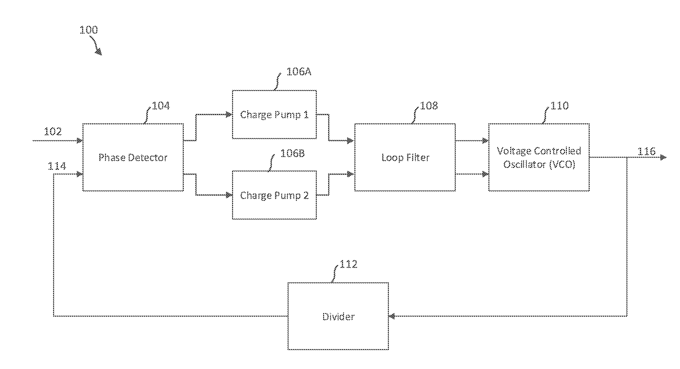
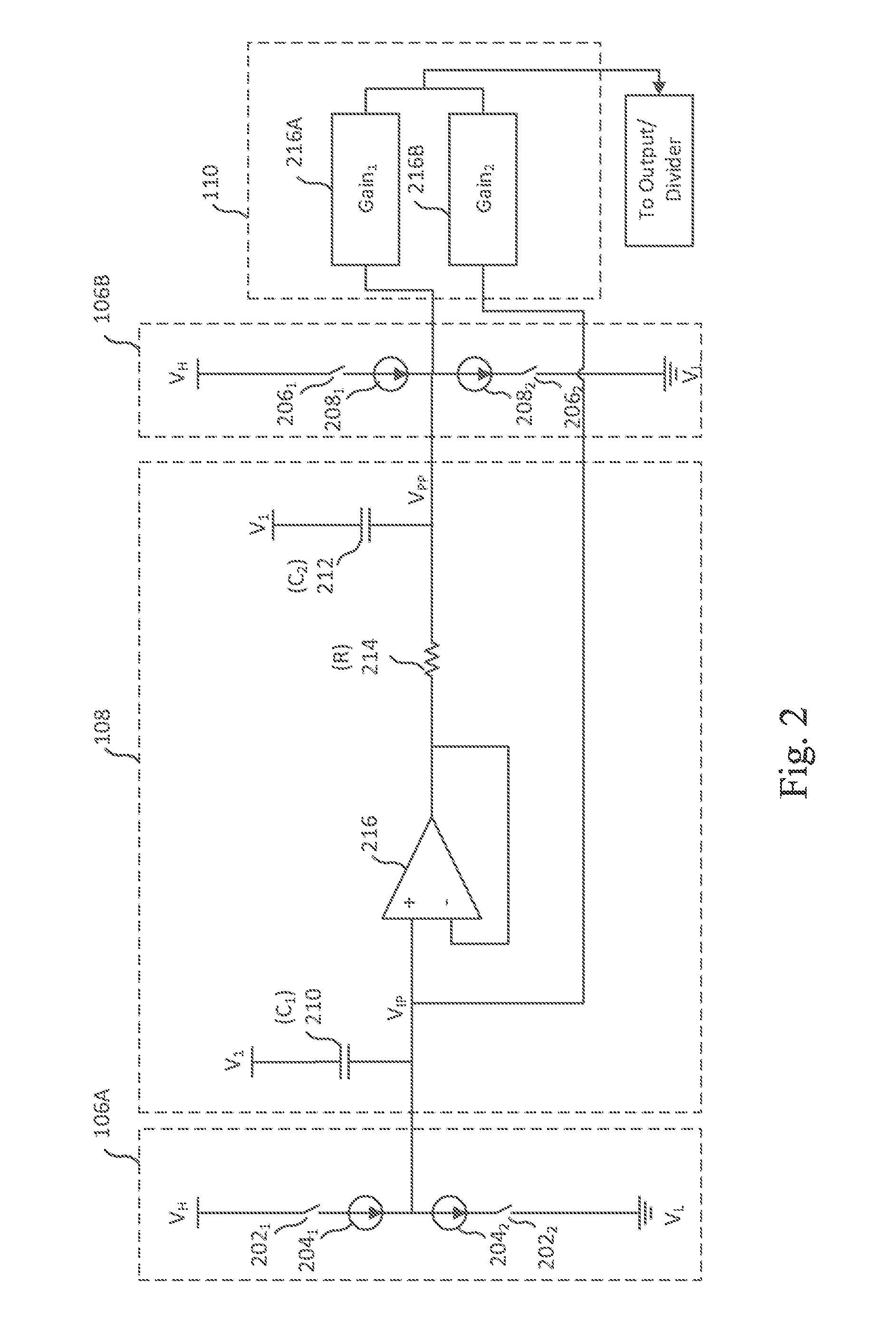
The patent describes a device called a phase-locked loop (PLL) that helps regulate the phase of a device's output signal. The PLL has a detector that detects the phase of the output signal and generates two currents, one larger than the other. It also has a loop filter and two separate filter paths, one of which reduces thermal noise. The PLL is connected to an oscillator that helps reduce the phase noise of the output signal. The technical effect of this invention is that it improves the accuracy and stability of the output signal for precise control over phase regulation in various applications.

Problems solved by technology

As PLL circuits are called upon to be employed in devices having faster speed requirements and having lower power supply voltages, electronic noise, such as thermal noise, and device size become larger factors in the design of the PLL.

Method used


Image

  • Capacitance Multiplier and Loop Filter Noise Reduction in a PLL
  • Capacitance Multiplier and Loop Filter Noise Reduction in a PLL
  • Capacitance Multiplier and Loop Filter Noise Reduction in a PLL

Examples


Embodiment Construction

[0014]The making and using of the present embodiments are discussed in detail below. It should be appreciated, however, that the present disclosure provides many applicable inventive concepts that can be embodied in a wide variety of specific contexts. The specific embodiments discussed are merely illustrative of specific ways to make and use the disclosed subject matter, and do not limit the scope of the different embodiments.

[0015]Embodiments will be described with respect to embodiments in a specific context, namely a phase-locked loop (PLL) and a method of operating a PLL. Some of the various embodiments described herein include a PLL for use in a radio frequency (RF) transceiver, telecommunications, computers, or any system which can utilize a PLL. In other embodiments, aspects may also be applied to other applications involving any type of PLL according to any fashion known in the art.

[0016]In general terms, using embodiments of the present disclosure, devices can leverage a P...


PUM


Abstract

According to an embodiment, a circuit includes a first charge pump configured to generate a first current at a first node, a second charge pump configured to generate a second current at a second node, a loop filter coupled between the first and second nodes, the loop filter including a first filter path coupled to the first node, a second filter path coupled to the second node, and an isolation buffer interposed between the first and second filter paths. The second current at the second node is different than the first current at the first node. The circuit further includes an oscillator configured to apply a first gain to an output of the first filter path and a second gain to an output of the second filter path.

Description

TECHNICAL FIELD[0001]The present invention relates generally to phase locked loops (PLLs), and, in particular to a design for a charge pump, a loop filter, and a voltage controlled oscillator (VCO) for a PLL.BACKGROUND[0002]Electronic devices of all kinds employ use of phase-locked loops (sometimes called phase lock loops) for manipulating electronic signals. A phase-locked loop (PLL) is a control system that generates an output signal having a phase and frequency that is related to the phase and frequency of an input signal (often called a reference signal). The circuit compares the phase of the input signal with the phase of the signal at the output and adjusts the frequency of an oscillator to keep the phase of the generated output signal matched to the phase of the input signal. By keeping the phases of these signals locked to each other, one can be assured that the frequency of the output signal also matches the frequency (or an integer multiple thereof) of the input signal.[00...

Claims


Application Information

Patent Timeline
Patent Type & Authority Applications(United States)
IPC IPC(8): H03L7/093H03L7/089
CPCH03L7/093H03L7/0893H03L7/089
Inventor LAHIRI, ABHIRUPGUPTA, NITIN
Owner STMICROELECTRONICS INT NV
Learn More