Eureka AIR delivers breakthrough ideas for toughest innovation challenges, trusted by R&D personnel around the world.

Nozzle having a variable neck section for a spacecraft thruster provided with a mobile needle

a technology of spacecraft and nozzle, which is applied in the direction of vessel construction, marine propulsion, aircraft navigation control, etc., can solve the problems of not being able to optimize the thrust coefficient in the prior art, and the single unvarying throat section is not suitable for a thruster, so as to achieve the effect of reducing such drawbacks

Active Publication Date: 2016-01-07
ARIANEGRP SAS
View PDF1 Cites 7 Cited by
  • Summary
  • Abstract
  • Description
  • Claims
  • Application Information

AI Technical Summary

Benefits of technology

The present invention aims to improve the performance of thrusters by designing a nozzle that can adjust its throat section to varying discharge rates. The invention introduces a needle that can define two operating modes for the throat, namely a high discharge rate mode and a low discharge rate mode. The needle is designed to optimize the thrust coefficient at different stages of operation of the thruster, while also providing good ability to withstand the temperature of the combustion gas. Additionally, the nozzle is relatively insensitive to heating and is able to adjust its gas ejection section independently from the structure holding it. Overall, the invention improves the efficiency and reliability of thrusters.

Problems solved by technology

Nevertheless, having recourse to a single unvarying throat section is not suitable for a thruster that has two rates of operation (typically a high discharge rate and a low discharge rate).
Nevertheless, variable throat section thrusters known in the prior art do not enable the thrust coefficients to be optimized both during a stage of operation at a high level of pressure in the thruster (corresponding to a high discharge rate) and during a stage of operation at a lower level of pressure in the thruster (corresponding to operating at a low discharge rate).

Method used


Image

  • Nozzle having a variable neck section for a spacecraft thruster provided with a mobile needle
  • Nozzle having a variable neck section for a spacecraft thruster provided with a mobile needle

Examples


Embodiment Construction

[0020]The invention relates to any aerospace vehicle thruster (for a missile, a launcher, or a satellite) operating on the principle of providing thrust by reaction or by ejecting gas.

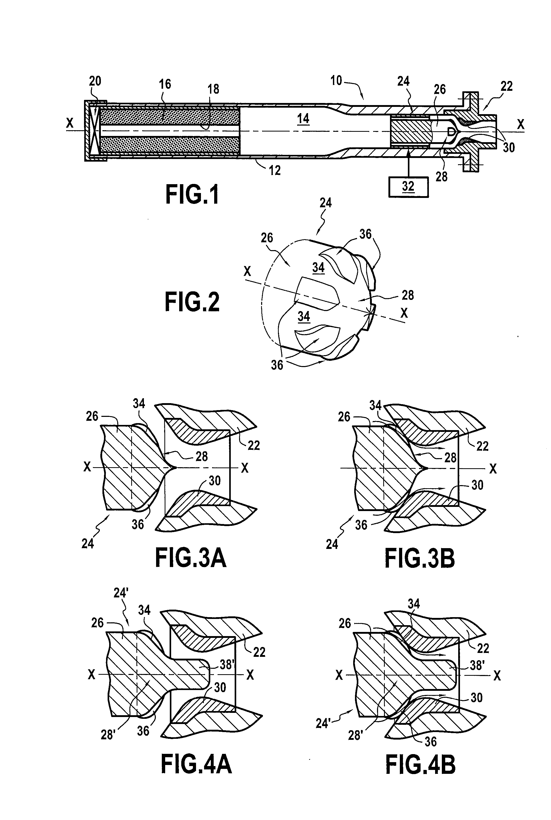
[0021]FIG. 1 is a very diagrammatic view of a non-limiting example of the invention being applied to a solid propellant thruster 10. Naturally, the invention also applies to thrusters using propellants in other forms (liquid, solid, or hybrid).

[0022]In known manner, the thruster 10 shown in FIG. 1 mainly comprises an outer shell 12 of substantially cylindrical shape containing a housing 14 also of cylindrical shape.

[0023]At a front end of the thruster, the housing 14 contains the propellant, e.g. in the form of a block of powder 16 that extends towards the front (along a longitudinal axis X-X of the thruster).

[0024]The block of powder 16 is pierced by a channel 18 situated on the longitudinal axis X-X of the thruster, this channel acting as a combustion chamber. An ignitor 20 mounted at the front end o...


PUM


Abstract

A nozzle of variable throat section for an aerospace vehicle thruster, the nozzle including a cylindrical housing presenting a throat of aperture diameter less than the diameter of the housing, and a needle suitable for sliding inside the housing between a high discharge rate front position in which the nose is set back from the throat of the housing, and a low discharge rate rear position in which the nose is in abutment against the throat, the needle including a rod for sliding inside the housing of the nozzle, the rod terminating in a nose of decreasing diameter. The nose of the rod is suitable for coming into abutment against the throat of the nozzle housing forming a seat and includes at least two axial grooves formed in its outer periphery to allow gas to pass when the nose is axially in abutment against the throat of the housing of the nozzle.

Description

BACKGROUND OF THE INVENTION[0001]The present invention relates to the general field of thrusters for delivering thrust for driving aerospace vehicles such as missiles, launchers, or indeed satellites, using the principle of propulsion by reaction or by ejecting gas. The invention relates more precisely to the fixed-throat nozzles fitted to solid propellant thrusters.[0002]A solid propellant thruster is mainly constituted by a shell containing a block of powder (propellant), an ignitor, and a nozzle with a fixed diverging portion. The block of powder is pierced by a channel lying on the axis of the thruster that acts as a combustion chamber. The ignitor ignites the powder at one end of the shell and combustion of the propellant propagates from the front towards the rear of the thruster. The powder burns at a predefined rate, thereby producing combustion gas that is expelled via the nozzle.[0003]The throat section of the nozzle makes it possible to control the combustion of the block ...

Claims


Application Information

Patent Timeline
Patent Type & Authority Applications(United States)
IPC IPC(8): F02K9/86F02K1/08F02K9/80
CPCF02K9/86F02K1/08F02K9/805F02K9/26
Inventor CLERMONT, MATHIEUSORGEON, SYLVAINLARRIEU, JEAN-MICHEL
Owner ARIANEGRP SAS
Why Eureka
Eureka Blog
Learn More