Eureka AIR delivers breakthrough ideas for toughest innovation challenges, trusted by R&D personnel around the world.

Ocean exploration apparatus and ocean exploration method

Active Publication Date: 2016-01-07
YBM
View PDF5 Cites 12 Cited by
  • Summary
  • Abstract
  • Description
  • Claims
  • Application Information

AI Technical Summary

Benefits of technology

The invention proposes an ocean exploration apparatus and method that can move in the sea using a glider type wing section and measure the electromagnetic field on the ocean bottom. The apparatus includes a probe body, buoyancy adjusting section, posture adjusting section, position information acquiring section, sensor section, and control section. The sensor section can measure the electromagnetic field through an electrode provided on the probe body and by adjusting its velocity and direction, the apparatus can navigate to a specific measurement point and measure the electromagnetic field there. This can help to better understand and explore the ocean and its resources.

Problems solved by technology

However, in the ocean bottom electromagnetometer of the related art, the dropping and recovery work of the ocean bottom electromagnetometer causes a burden, which causes a problem when performing exploration in a broad sea area.

Method used


Image

  • Ocean exploration apparatus and ocean exploration method
  • Ocean exploration apparatus and ocean exploration method
  • Ocean exploration apparatus and ocean exploration method

Examples


first embodiment

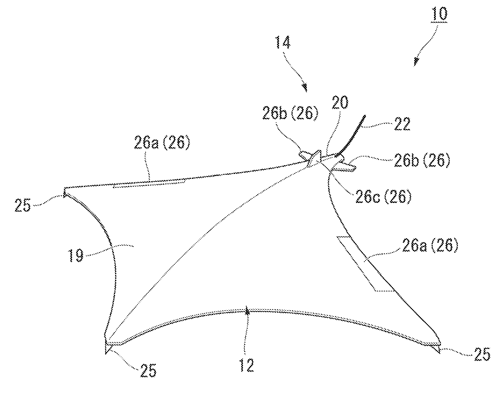
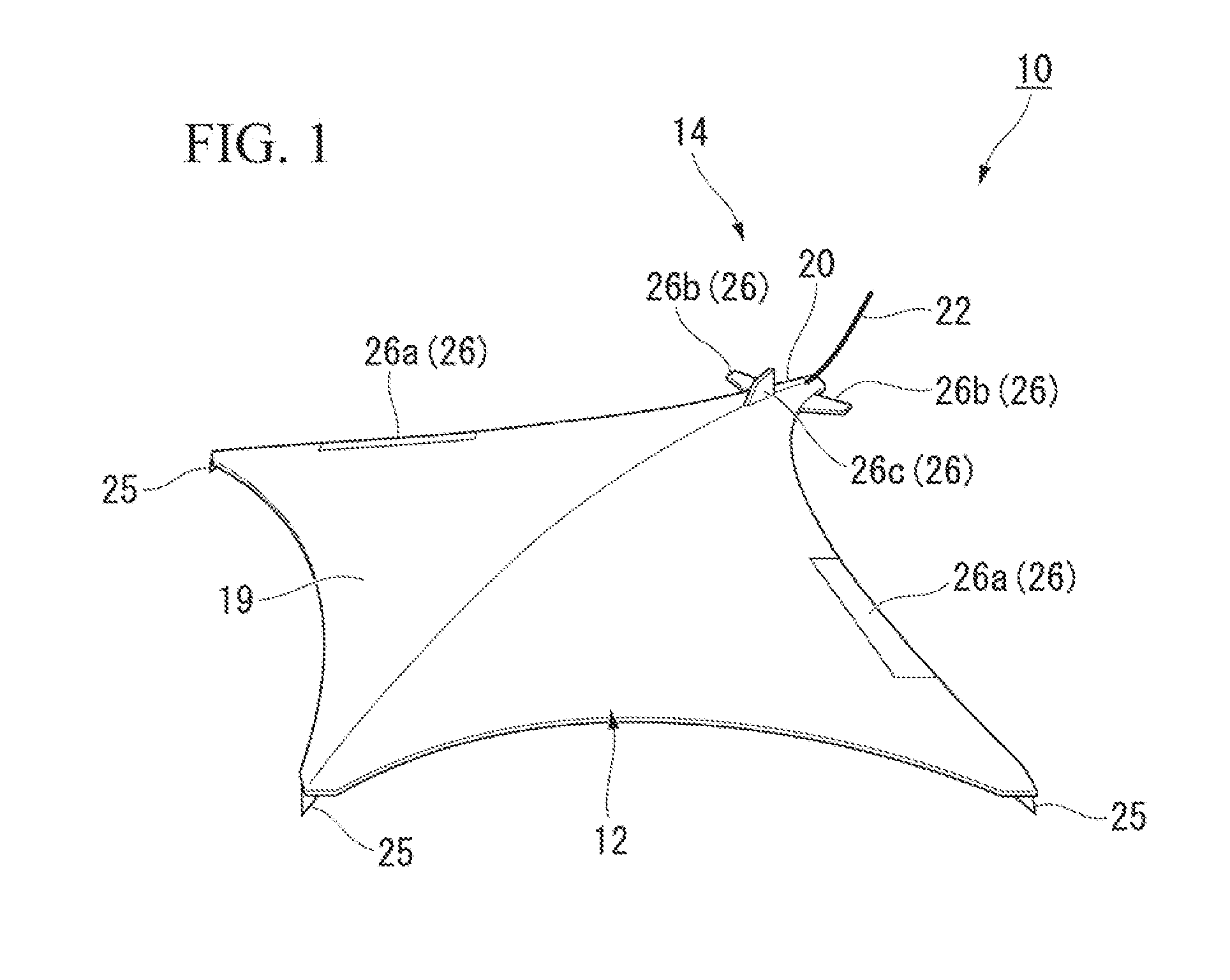
[0021]Hereinafter, an ocean exploration apparatus 10 according to a first embodiment of the invention will be described with reference to the accompanying drawings. The ocean exploration apparatus 10 is a glider type autonomous underwater vehicle (AUV) observation system mounted with a small magnetic sensor and is an autonomous underwater vehicle that explores an electromagnetic field of the ocean (marine magnetotelluric method (MT) AUV: MaMTA).

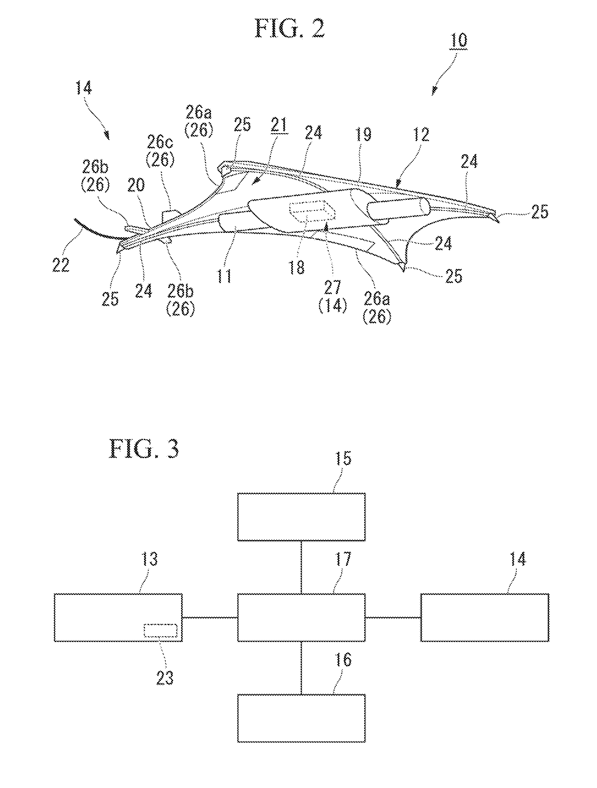
[0022]As shown in FIGS. 1 to 3, the ocean exploration apparatus 10 includes a probe body 11, a wing section 12, a sensor section 13, a posture adjusting section 14, a buoyancy adjusting section 15, a position information acquiring section 16, and a control section 17.

[0023]The probe body 11 is formed in a flat box shape. The probe body 11 is formed in a rectangular shape in which side portions extend along both of a longitudinal direction and a transverse direction in a planar view. A power source 18 is built into the probe body 11. For examp...

second embodiment

[0067]Next, an ocean exploration apparatus 30 according to a second embodiment of the invention will be described with reference to FIG. 5.

[0068]In the second embodiment, the same reference numerals are given to the same sections as the components in the first embodiment, description thereof will not be repeated, and only different points will be described.

[0069]The ocean exploration apparatus 30 according to the present embodiment further includes a transmitting section 31 that transmits electromagnetic waves. The transmitting section 31 includes an oscillation circuit 32 that extends in the circumferential direction to surround an outer peripheral edge of the wing section 12 over the entire periphery, and transmits electromagnetic waves toward the ocean bottom B in a state where the ocean exploration apparatus 30 is grounded on the ocean bottom B. Thus, it is possible to forcibly generate fluctuation in electromagnetic waves on the ocean bottom B, and to measure the fluctuation by...


PUM


Abstract

An ocean exploration apparatus including: a probe body; a buoyancy adjusting section that adjusts buoyancy generated in the probe body; a posture adjusting section that adjusts a posture of the probe body; a position information acquiring section that acquires position information of the probe body; a wing section that moves the probe body using a lifting force applied from seawater; a sensor section that is provided in the probe body and measures an electromagnetic field; and a control section that controls operations of the buoyancy adjusting section, the posture adjusting section, the position information acquiring section, and the sensor section according to predetermined conditions.

Description

[0001]This invention claims priority based on U.S. Patent Provisional Application No. 62 / 019,438 filed Jul. 1, 2014, the contents of which are herein incorporated by reference.BACKGROUND OF THE INVENTION[0002]1. Field of the Invention[0003]The present invention relates to an ocean exploration apparatus and an ocean exploration method.[0004]2. Description of Related Art[0005]In the related art, an ocean bottom electromagnetometer (OBEM) as disclosed in URL: http: / / obem.jpn.org / obem / obem025.html (GOTO, Tadanori “A Marine EM Researcher”) is known. The ocean bottom electromagnetometer is an ocean bottom installation type measurement apparatus used for exploration of an ocean bottom electromagnetic field, and measures an electric field and a magnetic field (electromagnetic field) that change over time. The ocean bottom electromagnetometer detects a feeble electric potential difference on the ocean bottom using arms with a length of 5 to 6 m on both sides. An electrode for electric potent...

Claims


Application Information

Patent Timeline
Patent Type & Authority Applications(United States)
IPC IPC(8): B63G8/00G01V3/15G01V3/40B63G8/14
CPCB63G8/001B63G8/14G01V3/15G01V3/40B63G2008/004B63G8/22B63G2008/002B63H19/04Y02T70/5236G01V1/30G01V1/38
Inventor MIZUNAGA, HIDEKIYAMAGUCHI, SATORU
Owner YBM
Why Eureka
Eureka Blog
Learn More