
Hemostatic agent applicator

a technology of hemostatic agent and applicator, which is applied in the field of hemostatic agent applicator, can solve the problems of obstructing the field of vision, applying gel to the incision surface, and affecting the effect of hemostatic agent removal, so as to reduce the amount of used hemostatic agent, effectively achieve hemostasis, and efficiently dispose of fluid hemostatic agen

Active Publication Date: 2016-01-07
FUSO PHARMA INDS +1
View PDF8 Cites 3 Cited by
  • Summary
  • Abstract
  • Description
  • Claims
  • Application Information

AI Technical Summary

Benefits of technology

The invention is about a device that can stop bleeding after it is applied. This means that less fluid hemostatic agent is needed and the risk of infectious disease is reduced. The device is easy to use and can be discarded after use, reducing manufacturing costs.

Problems solved by technology

However, such materials contain components derived from a living body, and thus need to be handled as carefully as a blood product is handled in terms of infectiousness.
On the other hand, the agent has a property of gel during application, and thus there is a problem that the agent is applied to an incision surface which is not horizontal.
The problem occurs since there is concern that the applied gel may flow out of the incision surface due to gravity.
However, the hemostatic agent containing power has a problem in that power scatters when the hemostatic agent is applied, thereby obstructing the field of vision.

Method used


Image

  • Hemostatic agent applicator
  • Hemostatic agent applicator
  • Hemostatic agent applicator

Examples


example 1

Fabrication of a Hemostatic Agent Applicator

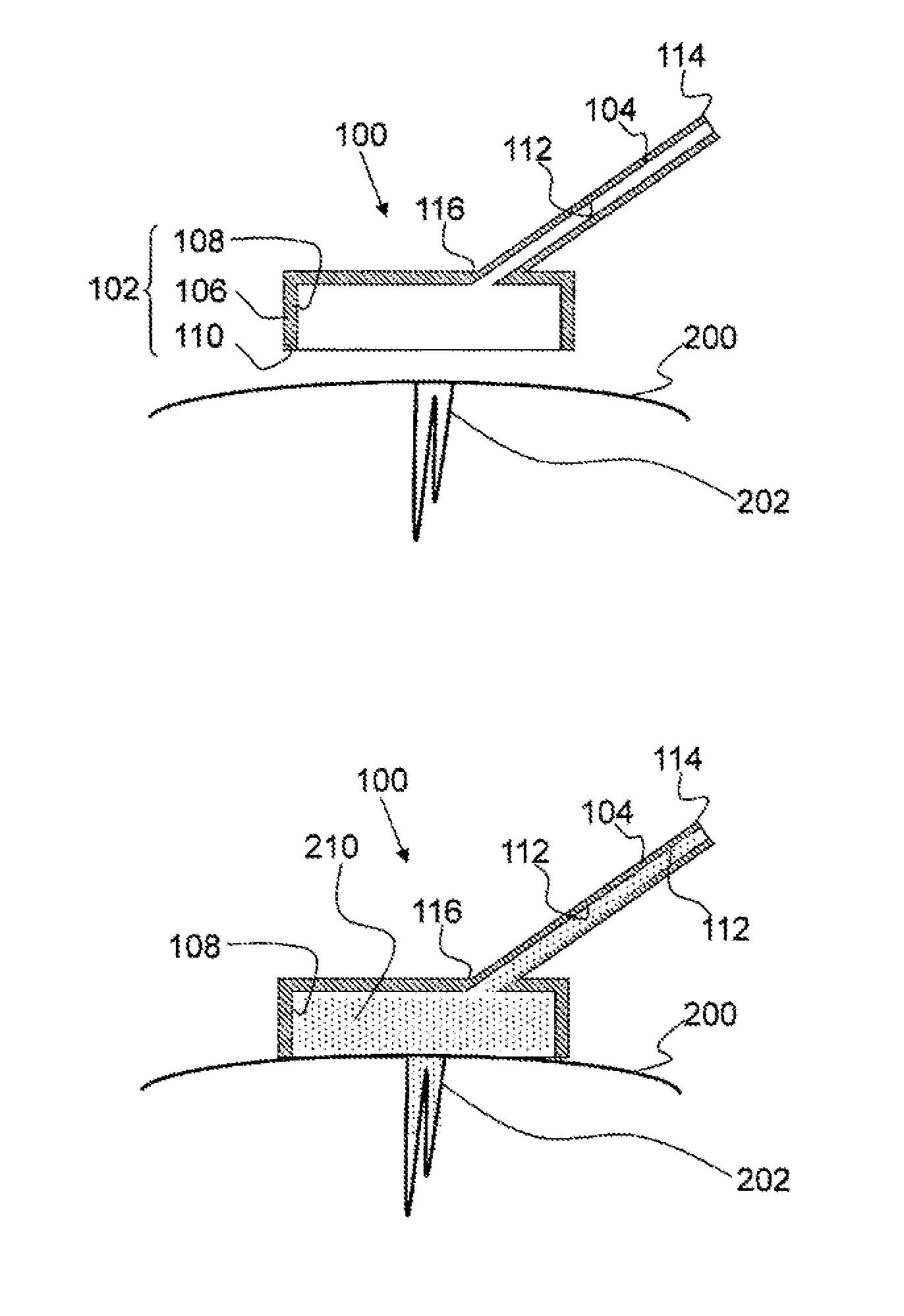
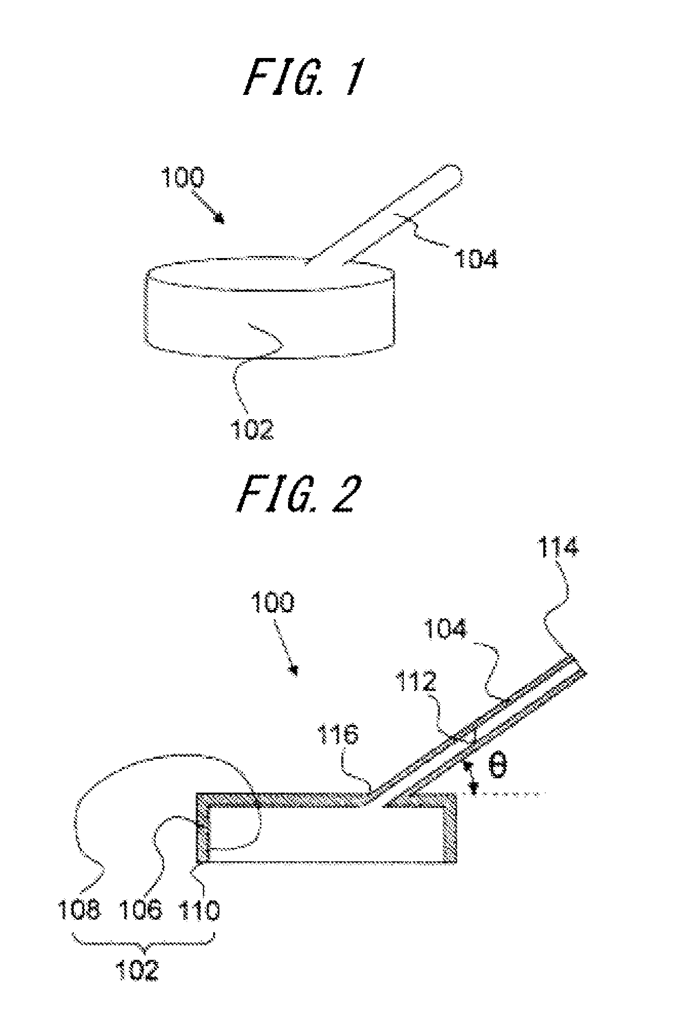
[0086]The hemostatic agent applicator 100 illustrated in FIGS. 1 and 2 is manufactured as below, for example.

[0087]A polypropylene inlet having a length of 20 mm and an internal diameter of 2 mm is attached to a cylindrical tool body, which has a height of 7 mm and an internal diameter of 15 mm and has one open end, made of a transparent polymethylmethacrylate resin using a cyano acrylate adhesive such that the angle θ illustrated in FIG. 2 becomes 45°. Further, a skirt made of a silicone resin is mounted on a side of the open end part of the tool body by tightening. A top plate of the tool body is provided with an outlet having a diameter of 1 mm. In this way, the example of the hemostatic agent applicator 100 illustrated in FIGS. 1 and 2 is manufactured.

example 2

Hemostasis of an Incision Site of a Rabbit Using a Hemostatic applicator

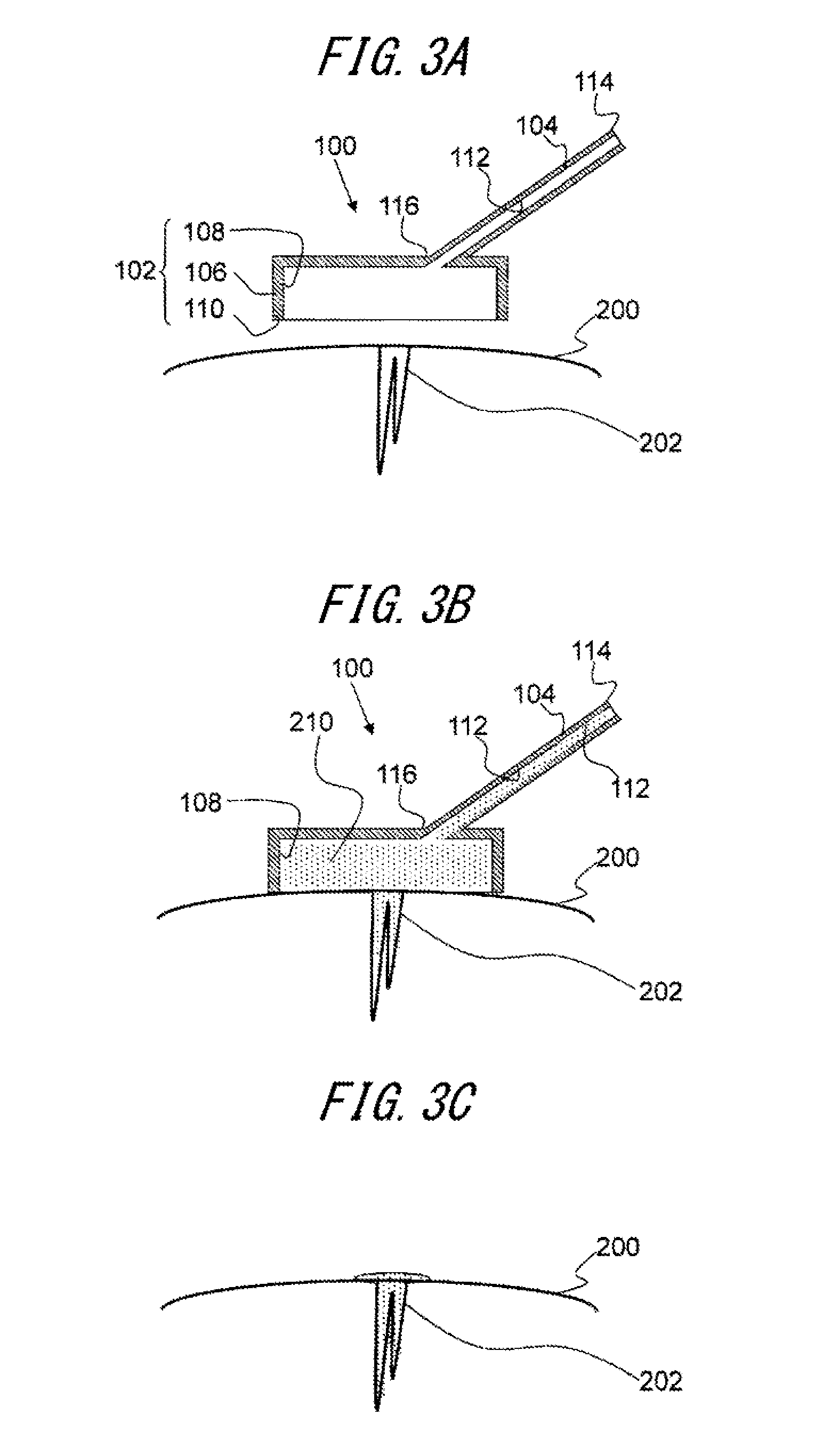
[0088]An abdomen of a rabbit (Japanese white color species) put under general anesthesia is cut open, a liver is exposed, and an incision is made on the surface of the liver using scissors. The incision site is maintained at inclined angles of 0°, about 30°, and about 60°, and the skirt of the applicator fabricated in Example 1 is closely pressed against an affected part. In this state, the space of the tool body is filled with a fluid hemostatic agent (about 1 mL) manufactured by a method disclosed in Patent Literature 1 through the inlet of the applicator, and the pressed state is maintained for two minutes. Thereafter, the applicator is removed, and whether the fluid hemostatic agent flows out is verified while the inclination of the incision site is maintained. Based on whether the fluid hemostatic agent flows out, hemostatic effect is determined to be “strong” or “weak”.

[0089]A result of determination is sh...


PUM


Abstract

Disclosed is a hemostatic agent applicator capable of effectively placing a fluid hemostatic agent on an incision surface. The present invention is a hemostatic agent applicator for use in disposing a fluid hemostatic agent, including a tool body in which a hollow part surrounded by a wall part is formed and which includes an open end part on a downstream side of the wall part, and an inlet provided to a portion of the wall part of the tool body to communicate with the hollow part. This hemostatic agent applicator is useful in medical settings relating to surgical procedures, particularly for surface bleeding of a liver and internal organ surgery such as a spleen and fibroid enucleation. An applicator further reduced in size can be applied not only in abdominal surgery, but in endoscopic surgery as well.

Description

TECHNICAL FIELD[0001]The present invention relates to a hemostatic agent applicator and, more specifically, to a hemostatic agent applicator capable of effectively disposing a hemostatic agent such as a gelatinous hemostatic agent which is used during surgery on a bleeding surface to stop the bleeding.BACKGROUND ART[0002]A hemostatic agent (material) for a living body and a biomedical adhesive (material) have been widely used as medicinal supplies or medical equipment in surgical operations, and the usefulness thereof has been established. However, such materials contain components derived from a living body, and thus need to be handled as carefully as a blood product is handled in terms of infectiousness.[0003]A non-living body-derived hemostatic agent that contains complete chemosynthesis peptide as a component has been developed (Patent Literature 1 to 3). The non-living body-derived hemostatic agent is useful in terms of avoiding infection when compared to a living body-derived ...

Claims


Application Information

Patent Timeline
Patent Type & Authority Applications(United States)
IPC IPC(8): A61B17/00A61M39/22
CPCA61B17/00491A61M2039/229A61M39/22A61B17/132A61B2017/00544A61B2017/12004A61M35/00
Inventor NAKAJIMA, KIYOKAZUYAMAMOTO, KEIICHI
Owner FUSO PHARMA INDS
Learn More