
Full duplex operation in a wireless communication network

a wireless communication network and full duplex technology, applied in data switching networks, frequency-division multiplexes, instruments, etc., can solve problems such as inter-ue path loss, inter-device interference, and interference between half duplex nodes

Active Publication Date: 2015-12-31
QUALCOMM INC
View PDF6 Cites 72 Cited by
  • Summary
  • Abstract
  • Description
  • Claims
  • Application Information

AI Technical Summary

Benefits of technology

The present patent provides methods, apparatus, and computer software for wireless communication networks that allow for full duplex communication between devices and limited (quasi-) full duplex communication between devices. The patent also discusses methods for determining an inter-device path loss between devices and co-scheduling devices to utilize a shared time-frequency resource. The technical effects of the patent include improved communication speed and efficiency between devices and reduced interference between devices.

Problems solved by technology

In such a network, where full duplex nodes communicate with half duplex nodes, interference between the half duplex nodes can become problematic.
In this case, co-scheduling the UEs can cause the transmission from the second UE 306 to produce cross-device interference that affects the receiving performance of the first UE 304.
Further, the inter-UE path loss may be affected by other potentially random phenomena, such as shadowing.
Accordingly, the selected devices may utilize the allocated resource and may discover inter-device interference between pairs of devices.
On the other hand, if the geographic distance between two UEs is relatively small (e.g., less than the threshold), then their path loss may or may not be high enough.
However, in other aspects of the disclosure, one or more UEs in the wireless communication system may be capable of supporting full duplex operation, at least to a limited extent.

Method used


Image

  • Full duplex operation in a wireless communication network
  • Full duplex operation in a wireless communication network
  • Full duplex operation in a wireless communication network

Examples


Embodiment Construction

[0034]The detailed description set forth below in connection with the appended drawings is intended as a description of various configurations and is not intended to represent the only configurations in which the concepts described herein may be practiced. The detailed description includes specific details for the purpose of providing a thorough understanding of various concepts. However, it will be apparent to those skilled in the art that these concepts may be practiced without these specific details. In some instances, well known structures and components are shown in block diagram form in order to avoid obscuring such concepts.

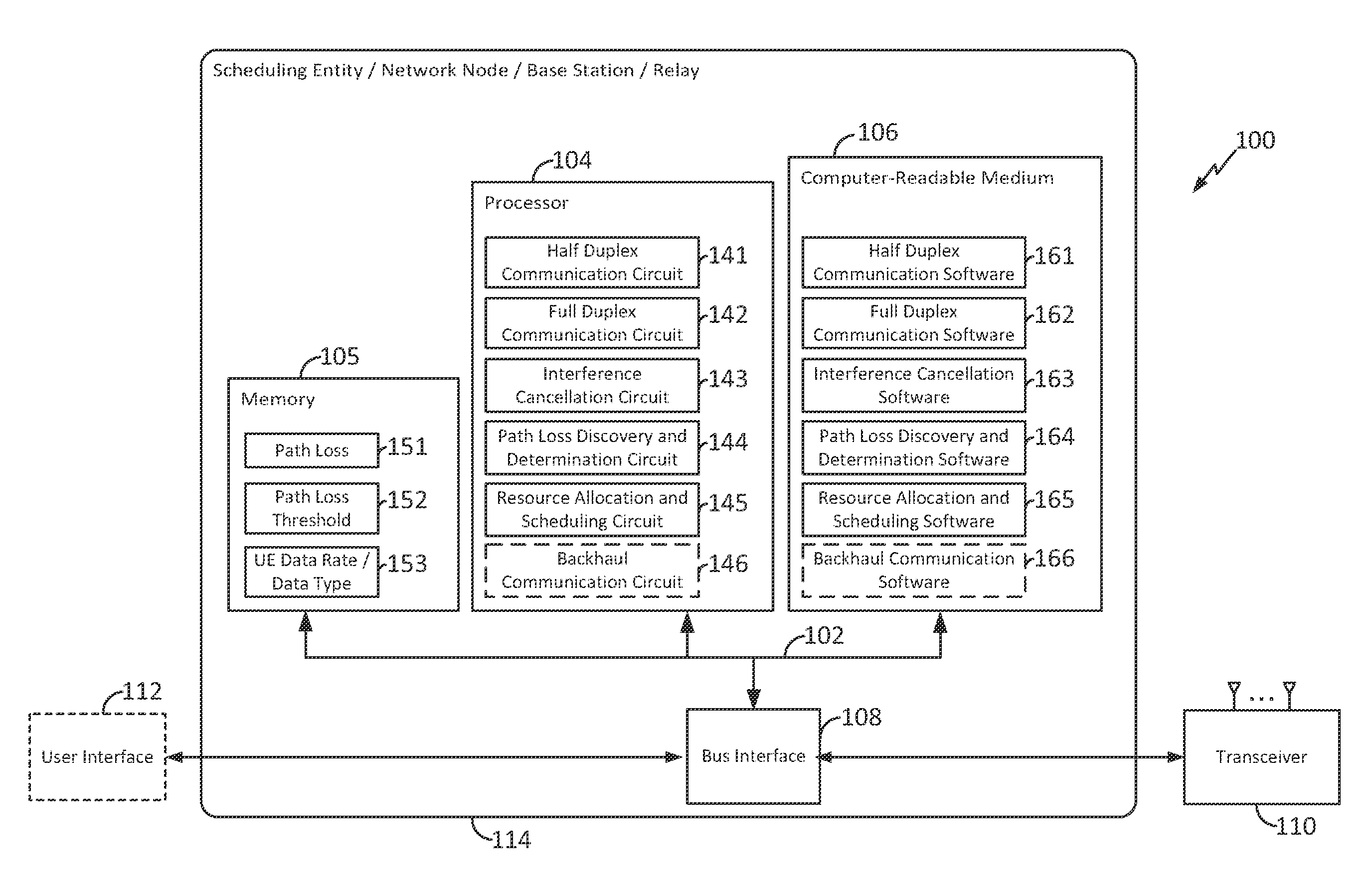
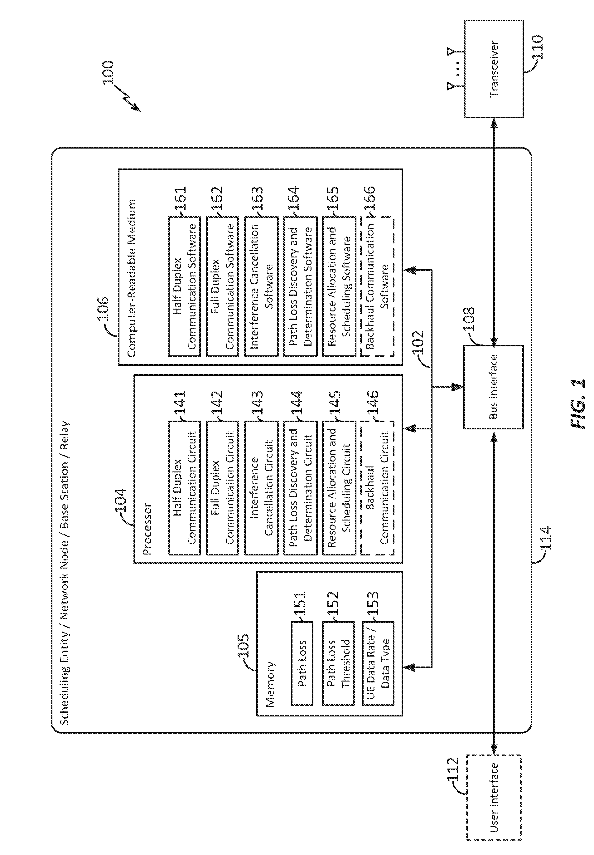
[0035]FIG. 1 is a block diagram illustrating an example of a hardware implementation for an apparatus 100 employing a processing system 114. In accordance with various aspects of the disclosure, an element, or any portion of an element, or any combination of elements may be implemented with a processing system 114 that includes one or more processors 104. ...


PUM


Abstract

Methods, apparatus, and computer software are disclosed for communicating within a wireless communication network including a scheduling entity configured for full duplex communication, and user equipment (UE) configured for half duplex communication. In some examples, one or more UEs may be configured for limited (quasi-) full duplex communication. Some aspects relate to scheduling the UEs, including determining whether co-scheduling of the UEs to share a time-frequency resource is suitable based on one or more factors such as an inter-device path loss.

Description

CROSS-REFERENCE TO RELATED APPLICATIONS[0001]This application claims priority to and the benefit of provisional patent application No. 62 / 017,182, filed in the United States Patent and Trademark Office on Jun. 25, 2014, the entire content of which is incorporated herein by reference as if fully set forth below and for all applicable purposes.TECHNICAL FIELD[0002]Aspects of the present disclosure relate generally to wireless communication systems, and more particularly, to scheduling algorithms for wireless communication systems that combine full duplex nodes and half duplex nodes.BACKGROUND[0003]Wireless communication networks are widely deployed to provide various communication services such as telephony, video, data, messaging, broadcasts, and so on. Such networks, which are usually multiple access networks, support communications for multiple users by sharing the available network resources. In many networks, resources are allocated for bi-directional communication utilizing eith...

Claims


Application Information

Patent Timeline
Patent Type & Authority Applications(United States)
IPC IPC(8): H04W72/12H04W52/24H04L5/00H04W24/08H04L5/14H04L5/16H04W72/54
CPCH04L5/0005H04L5/0096H04L5/14H04L5/16H04W72/121H04W52/243H04W72/1289H04W72/082H04W24/08H04W72/541H04W72/23
Inventor BHUSHAN, NAGAJI, TINGFANGMUKKAVILLI, KRISHNA KIRANSORIAGA, JOSEPHANG, PETER PUI LOK
Owner QUALCOMM INC
Learn More