
Biosensor incorporating protein-immobilized membrane and method of immobilizing protein in biosensor

a biosensor and membrane technology, applied in the field of biosensors incorporating protein-immobilized membranes and biosensor immobilization methods, can solve the problems of low efficiency of oxidoreductase (active site), inability to immobilize in a manner, and inability to efficiently utilize oxidoreductase, etc., to achieve efficient and advantageous activity, good orientation

Active Publication Date: 2015-12-31
ARKRAY INC
View PDF2 Cites 0 Cited by
  • Summary
  • Abstract
  • Description
  • Claims
  • Application Information

AI Technical Summary

Benefits of technology

[0015]An object of the present invention is to immobilize a protein such as oxidoreductase with good orientation and to cause the activity to be exhibited efficiently and advantageously in terms of cost with the use of a small amount of enzyme.
[0016]Another object of the present invention is to provide a biosensor which is capable of properly measuring the concentration of a substrate such as glucose without using an electron mediator.

Problems solved by technology

However, with the conventional oxidoreductase-immobilizing methods described above, oxidoreductase fails to be immobilized in a manner such that the active sites are oriented (located) to exhibit efficient activity of the oxidoreductase.
In other words, the conventional methods have a drawback that the immobilization is not performed with the orientation of the oxidoreductase being controlled.
As a result, the ratio of the oxidoreductase (active site) which can be utilized efficiently is relatively low.
Thus, to exhibit the intended function of the immobilized oxidoreductase, the amount of oxidoreductase to be loaded needs to be increased, which is disadvantageous in terms of cost.
Particularly, since oxidoreductases are generally expensive, the increase in the amount of oxidoreductase to be loaded leads to a considerably disadvantageous cost increase.
Moreover, since the orientation of oxidoreductase cannot be controlled, the ratio of the actually usable oxidoreductase varies among biosensors even when the same amount of oxidoreductase is loaded.
However, when the orientation of the oxidoreductase is random, the efficiency of electron transfer from the oxidoreductase to the working electrode is poor.
Therefore, the biosensor 9 provided by immobilizing oxidoreductase by a conventional method is disadvantageous in terms of cost, because it requires an electron mediator.
Further, as the electron mediator, metal complexes such as potassium ferrocyanide are used some of which have an adverse effect on the human body.
Thus, it is not desirable to use an electron mediator for such an analytical tool as the biosensor 9.

Method used


Image

  • Biosensor incorporating protein-immobilized membrane and method of immobilizing protein in biosensor
  • Biosensor incorporating protein-immobilized membrane and method of immobilizing protein in biosensor
  • Biosensor incorporating protein-immobilized membrane and method of immobilizing protein in biosensor

Examples


example 1

[0091]In this example, a carbon electrode, a phospholipid polymer layer and a CyGDH layer were formed on a surface of a PET substrate. The conditions of the surface before and after the formation of these layers were observed using an atomic force microscope (AFM) (Tradename “D-3100” available from Digital Instruments).

(Observation of the Carbon Electrode Surface)

[0092]The carbon electrode was formed by screen printing using a carbon ink available from Acheson Japan Ltd. The AFM image of the carbon electrode is shown in FIG. 6. As will be understood from FIG. 6, the surface of the carbon electrode had relatively large irregularities, with carbon particles (having average particle size of about 100 nm) appearing on the surface.

(Observation of the Phospholipid Polymer Layer Surface)

[0093]To form the phospholipid polymer layer, the surface of the carbon electrode was first subjected to VUV treatment (hydrophilic treatment). Then, MPC polymer solution was applied to the surface of the c...

example 2

[0097]In this example, responsiveness was examined with respect to an electrode (inventive electrode) to which CyGDH is immobilized via a phospholipid polymer layer and to an electrode (comparative electrode) to which CyGDH is immobilized without the intervention of a phospholipid polymer layer.

[0098]The inventive electrode was prepared by forming a phospholipid polymer layer on a carbon electrode and then immobilizing CyGDH, similarly to Example 1.

[0099]The comparative electrode was prepared similarly to the inventive electrode except that a phospholipid polymer layer was not formed.

[0100]The responsiveness of the inventive electrode and the comparative electrode was evaluated as the responsive current obtained when a voltage was applied to a glucose solution using a current measuring apparatus Y prepared as shown in FIG. 9.

[0101]The current measuring apparatus Y includes a working electrode Y1, a reference electrode Y2 and a counter electrode Y2, which are connected to a potentios...


PUM

PropertyMeasurementUnit
molecular weightaaaaaaaaaa
particle sizeaaaaaaaaaa

Abstract

The present invention relates to a protein-immobilized membrane (14) including a cell membrane homologous layer (14A) and a protein (14B) immobilized to the cell membrane homologous layer (14A), where the protein contains cytochrome or a cytochrome complex. The present invention also relates to a method for forming a protein-immobilized membrane (14), and an enzyme-immobilized electrode and a biosensor (X1) provided with a protein-immobilized membrane (14). Preferably, the cell membrane homologous layer (14A) may contain a phospholipid polymer, and the protein (14B) may be CyGDH including an α subunit having a glucose dehydrogenase activity and cytochrome C having a function of electron transfer.

Description

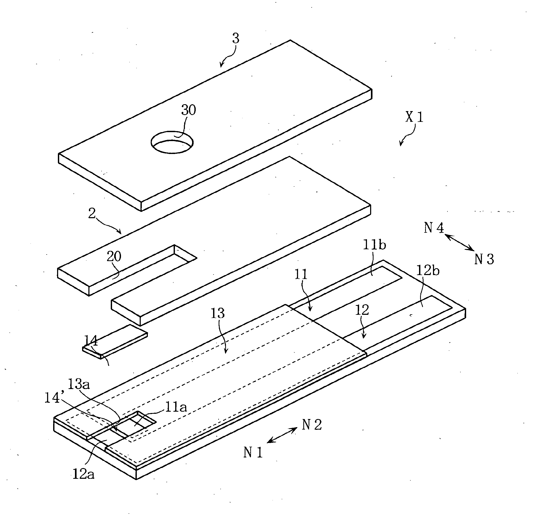
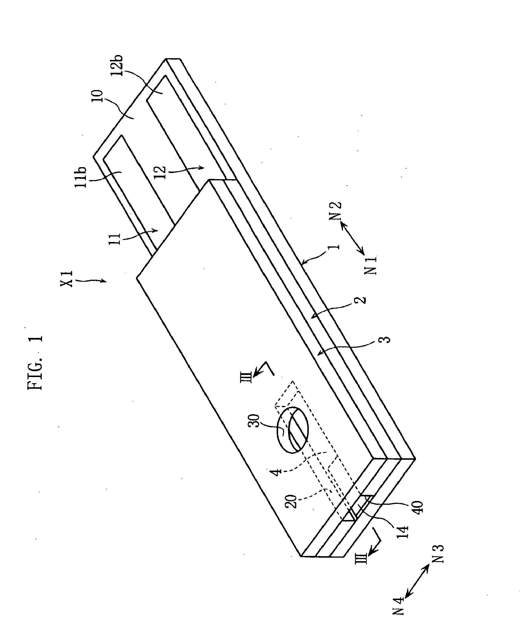
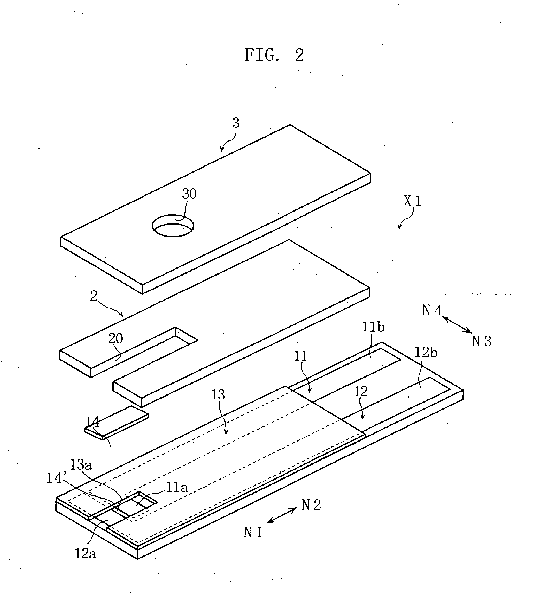
TECHNICAL FIELD[0001]The present invention relates to a technique for immobilizing a protein containing cytochrome to an immobilization target material.BACKGROUND ART[0002]Biosensors designed to analyze a sample by an electrochemical or optical method are widely used. An example of biosensors designed to analyze a sample by an electrochemical method (see Patent Document 1, for example) is a biosensor 9 shown in FIG. 12 of the present application.[0003]The illustrated biosensor 9 includes a substrate 92 formed with a working electrode 90 and a counter electrode 91, and a cover 94 bonded to the substrate via a spacer 93. The biosensor 9 further includes a flow path 95 defined by the substrate 92, the spacer 93 and the cover 94. The flow path 95 is used for moving a sample by capillary force and formed with a reagent portion 96.[0004]The reagent portion 96 connects the ends of the working electrode 90 and the counter electrode 91 and contains oxidoreductase. The oxidoreductase catalyze...

Claims


Application Information

Patent Timeline
Patent Type & Authority Applications(United States)
IPC IPC(8): G01N27/327C12N11/06C12N11/08
CPCC07K14/705C07K14/80C12N9/0006C12N11/08C12Q1/006G01N2333/80C12N11/06G01N27/3272C12N11/087
Inventor KATSUKI, KOJIYAMAOKA, HIDEAKI
Owner ARKRAY INC
Learn More