Magnetic resonance system and operating method therefor
- Summary
- Abstract
- Description
- Claims
- Application Information
AI Technical Summary
Benefits of technology
Problems solved by technology
Method used
Image
Examples
Embodiment Construction
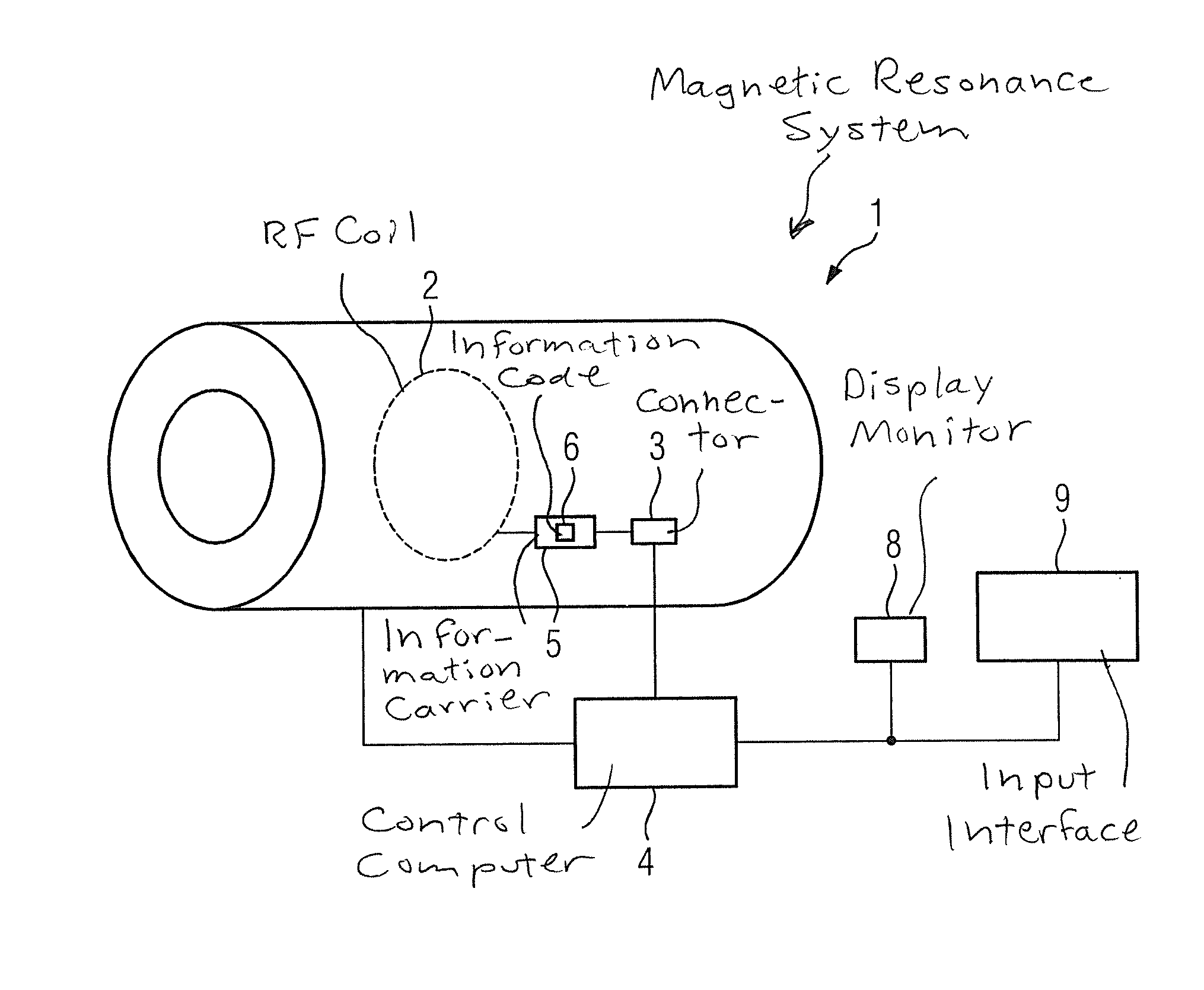
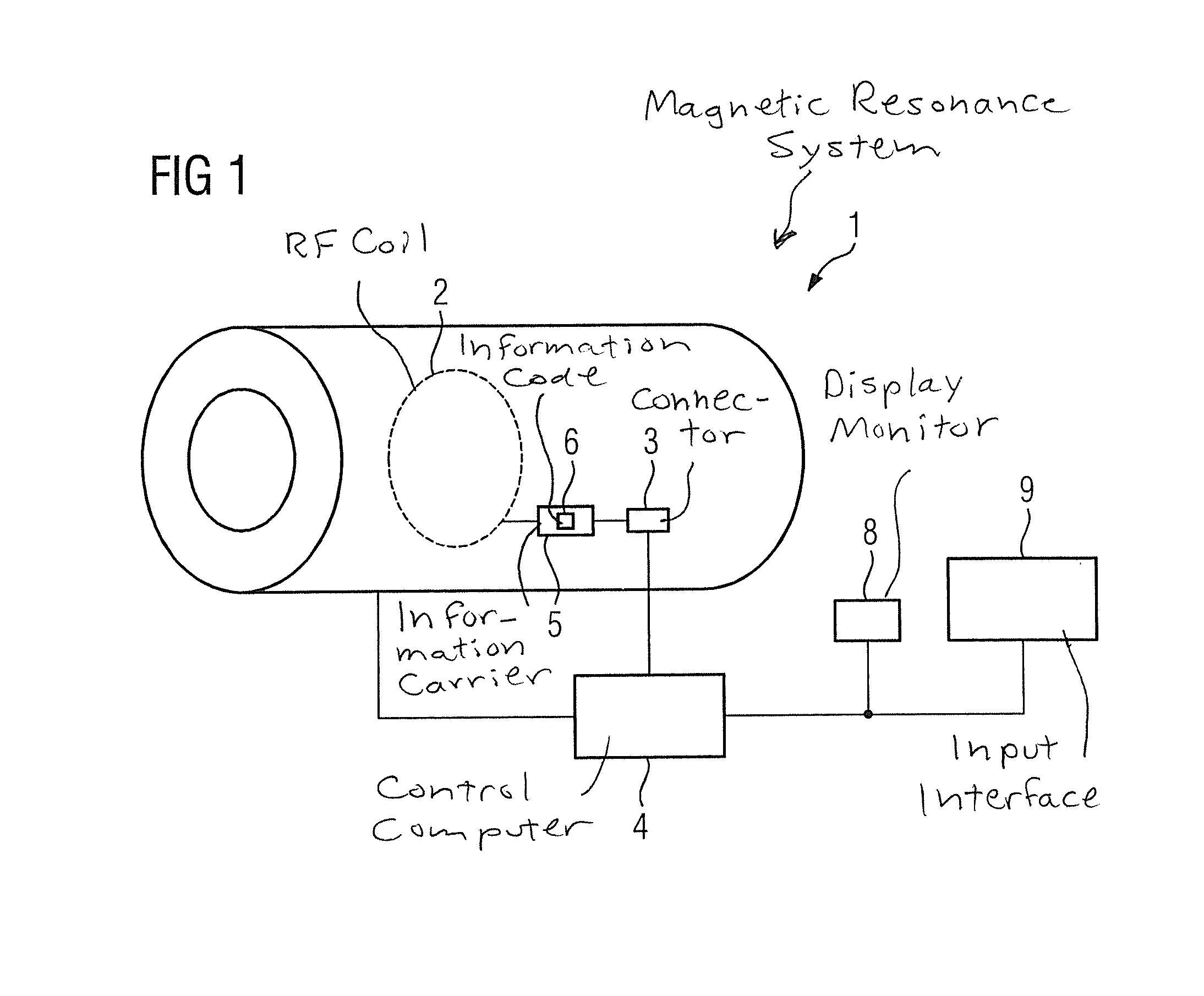
[0043]FIG. 1 shows a magnetic resonance system 1 that has a scanner with at least one radio-frequency (RF) coil 2. The radio-frequency coil 2 is connected via a connector 3 to the control computer 4 that operates the scanner of magnetic resonance system 1, wherein the connector 3 makes an electrical connection possible. The connector 3 can be embodied as a plug-in connection. The connector 3 makes it possible to connect various radio-frequency coils 2 to the control computer 4. This diagram is naturally simplified, more elements than the connector 3 are of course located between the radio-frequency coil 2 and the control computer 4 of the magnetic resonance system 1. The connector is important since it allows the exchange of different radio-frequency coils 2.
[0044]The radio-frequency coil 2 has an information carrier 5, which bears an information code 6. This information code 6 is coil identification information. For example the identification code 6 consists of a sequence of digits...
PUM
 Abstract
Description
Claims
Application Information
 - R&D Engineer
- R&D Manager
- IP Professional
- Industry Leading Data Capabilities
- Powerful AI technology
- Patent DNA Extraction
Browse by: Latest US Patents, China's latest patents, Technical Efficacy Thesaurus, Application Domain, Technology Topic, Popular Technical Reports.
© 2024 PatSnap. All rights reserved.Legal|Privacy policy|Modern Slavery Act Transparency Statement|Sitemap|About US| Contact US: help@patsnap.com


