Method for limiting a supply flow in a heat transfer system

a technology of heat transfer system and supply flow, which is applied in the direction of lighting and heating apparatus, heating types, instruments, etc., can solve the problems of increasing the energy consumption of the delivery pump, requiring quite a bit of effort to set such balancing valves, and only optimal setting, so as to achieve simple and improved hydraulic balancing

Active Publication Date: 2015-12-24
GRUNDFOS HLDG
View PDF13 Cites 21 Cited by
  • Summary
  • Abstract
  • Description
  • Claims
  • Application Information

AI Technical Summary

Benefits of technology

[0004]With regard to this state of the art, it is an object of the invention, to provide a method for limiting a supply flow in a heat transfer ...

Problems solved by technology

In heating installation with several heating circuits, for example floor heating systems with several heating circuits for example, there exists the problem of providing a hydraulic balancing between the several heating circuits.
This arrangement has the disadvantage that the setting is only optimal for one design point of the installation...

Method used


Image

  • Method for limiting a supply flow in a heat transfer system
  • Method for limiting a supply flow in a heat transfer system
  • Method for limiting a supply flow in a heat transfer system

Examples


Embodiment Construction

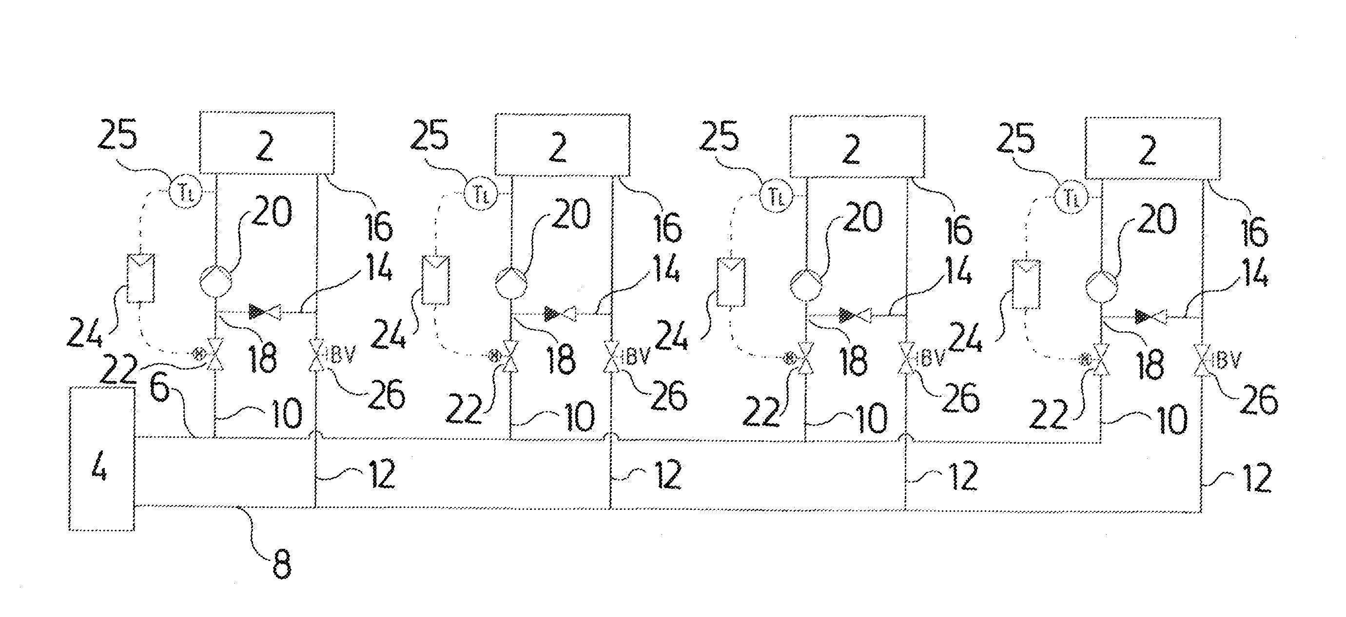
[0056]Referring to the drawings, FIG. 1 shows a conventional heat transfer system with four heating circuits, for example heating circuits of a floor heating. The four heating circuits each have heat transfer means for locations to be temperature-controlled, in the form of load circuits 2. These are supplied by a heat source 4 via a supply 3 or a supply circuit, which comprises a feed 6 and a return 8. Supply conduits 10 lead from the feed 6 to the individual load circuits 2, and accordingly return conduits 12 lead back to the return 8 of the supply circuit. In this case, mixing devices are provided in the supply to the load circuits 2, for the closed-loop control of the feed temperature in the load circuits 2 at the entry, i.e. of the load entry temperature TL. These mixing devices consist of a mixing connection or a mixing conduit 14 which connects the exits 16 of the load circuits 2 to a mixing point 18 in the supply conduit 10. The load circuits in each case comprise a load pump...


PUM


Abstract

A method for limiting a supply flow (qS) in a heat transfer system which includes a supply conduit (10) with a supply flow (qS) and with a supply entry temperature (TS), and at least one load circuit (2) with a load pump (20) which provides a load flow (qL) with a load entry temperature (TL) and a load exit temperature (TR). The load entry temperature (TL) is set by way of changing the supply flow (qS), wherein the supply flow (qS) is limited to a maximal flow (qS, max), taking into account at least one temperature detected in the load circuit (2). A heat transfer system, in which this method is realized, is also provided.

Description

CROSS REFERENCE TO RELATED APPLICATIONS[0001]This application claims the benefit of priority under 35 U.S.C. §119 of European Patent Application 14 173 714.8 filed Jun. 24, 2014, the entire contents of which are incorporated herein by reference.FIELD OF THE INVENTION[0002]The invention relates to a method for limiting a supply flow in a heat transfer system as well as in a heating or air-conditioning installation, as well as to such a heat transfer system.BACKGROUND OF THE INVENTION[0003]In heating installation with several heating circuits, for example floor heating systems with several heating circuits for example, there exists the problem of providing a hydraulic balancing between the several heating circuits. For this, it is known to provide a balancing valve in each heating circuit, with which balancing valve the flow through the respective heating circuit, i.e. in particular the supply flow through the heating circuit, can be limited. This arrangement has the disadvantage that...

Claims


Application Information

Patent Timeline
IPC IPC(8): F24D19/10
CPCF24D19/1006F24D19/1012F24D19/1015Y02B30/70
Inventor SKOVMOSE KALLESOE, CARSTENNIELSEN, BRIAN KONGSGAARD
Owner GRUNDFOS HLDG
Why Eureka
Try Eureka