Method for determining a spatially resolved distribution of a marker substance

a technology of spatial resolution and marker substance, applied in the field of method for determining the spatial resolution distribution of a marker substance, to achieve the effect of good limitation of the marker substance, particularly easy visualization, and particularly easy determination

Inactive Publication Date: 2015-12-24
SIEMENS AG
View PDF2 Cites 7 Cited by
  • Summary
  • Abstract
  • Description
  • Claims
  • Application Information

AI Technical Summary

Benefits of technology

[0023]One embodiment provides that the marker substance is adjusted in such a way to a tissue of the object under examination located in the examination region that the marker substance differs from a known tissue-n-tuple of the tissue by at least 20 percent in at least one material parameter of the marker substance n-tuple. The marker substance differs in particular in the at least one material parameter of the marker substance-n-tuple from the known tissue-n-tuple by at least 40 percent, preferably by at least 60 percent, advantageously by at least 80 percent, at most advantageously by at least 100 percent. The tissue-n-tuple may have been determined beforehand by means of a measurement or on account of a priori specialist knowledge relating to the material properties of the tissue. In this way the marker substance is adjusted particularly advantageously to the tissue for the visualization by means of the quantitative magnetic resonance method. A particularly good limitation of the marker substance by the tissue is namely possible. The marker substance can thus be visualized particularly easily. The adjustment of the marker substance to the tissue may include a suitable selection and / or change to the marker substance. The marker substance can contain protons or other magnetic resonance-visible nuclei, which have material parameters which differ sufficiently from the material parameters of the tissue. An addition of magnesium or iron oxide to the marker substance is conceivable for instance so that a T1 relaxation time and / or a T2 relaxation time of the marker substance is set and can advantageously be adjusted to the tissue.
[0024]One embodiment provides that the tissue located in the examination region is determined with the aid of a localization of the examination region in a body of the object under examination. Different tissue-n-tuples, which belong to different tissue types, can be stored in a database. Depending on the localization of the examination region in the body of the object under examination, the suitable tissue-n-tuple of the various tissue-n-tuples can then be loaded from the database for comparison with the marker substance-n-tuple. Alternatively or in addition, the suitable tissue type can also be determined with the aid of an item of information, in which tissue type the marker substance typically accumulates. If various tissue types are located in the examination region, various tissue-n-tuples can be loaded from the database for comparison with the marker substance-n-tuple. The tissue located in the examination region can thus be determined particularly easily and a comparison basis can be created for the measurement-n-tuple.
[0025]One embodiment provides that the measurement-n-tuple is compared with the marker substance-n-tuple and the tissue-n-tuple, and an assignment of the measurement-n-tuple to the marker substance-n-tuple or the tissue-n-tuple takes place with the aid of the result of the comparison. By comparison with the marker substance-n-tuple, the comparison of the measurement-n-tuple with the tissue-n-tuple also offers an advantageous possibility of determining whether the marker substance is located at a specific location. The tissue-n-tuple thus represents a reference basis which can be used to estimate the comparison of the measurement-n-tuple with the marker substance-n-tuple. If the measurement-n-tuple is assigned to the marker substance-n-tuple, it can be determined that the marker substance is located at the corresponding point in the spatially resolved distribution. If the measurement-n-tuple is assigned to the tissue-n-tuple, it can be determined that the marker substance is not located at the corresponding point in the spatially resolved distribution.
[0026]One embodiment provides that the assignment of the measurement-n-tuple to the marker substance-n-tuple or to the tissue-n-tuple takes place according to the criterion as to whether the material parameters of the measurement-n-tuple are more similar to the material parameters of the marker substance-n-tuple or to the material parameters of the tissue-n-tuple. A first similarity measure, which describes the similarity of the measurement-n-tuple and the marker substance-n-tuple and a second similarity measure which describes the similarity of the measurement-n-tuple and the tissue-n-tuple can be determined for instance. If the first similarly measure is greater than the second similarity measure, the assignment of the measurement-n-tuple to the marker substance-n-tuple can thus take place. If the second similarity measure is greater than the first similarity measure, the assignment of the measurement-n-tuple to the tissue-n-tuple can thus take place. Here the similarity measure can describe the degree of the deviation, for instance in percentage, of the two n-tuples. It can thus be particularly easily determined, whether the measurement-n-tuple is to be assigned to the marker substance-n-tuple or to the tissue-n-tuple.

Problems solved by technology

Such non-quantitative magnetic resonance images therefore typically only supply a qualitative contrast between different substances.

Method used


Image

  • Method for determining a spatially resolved distribution of a marker substance
  • Method for determining a spatially resolved distribution of a marker substance
  • Method for determining a spatially resolved distribution of a marker substance

Examples


first embodiment

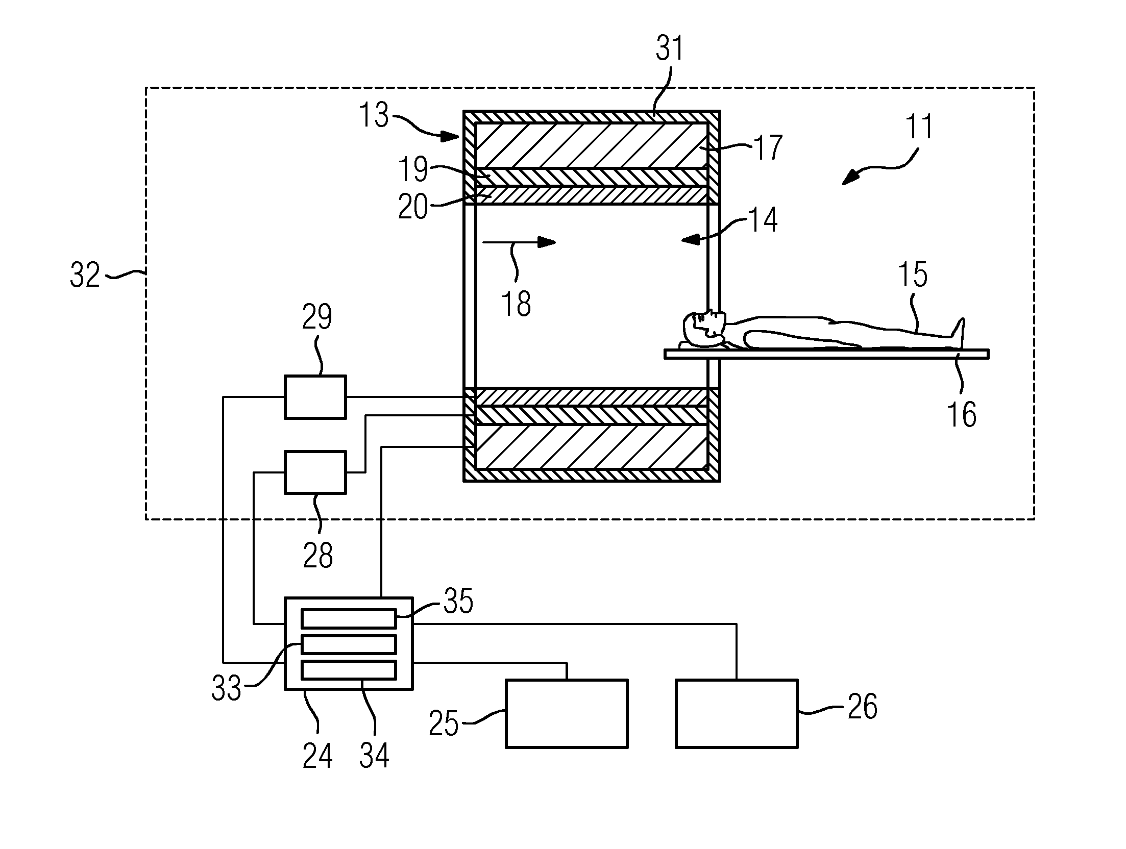
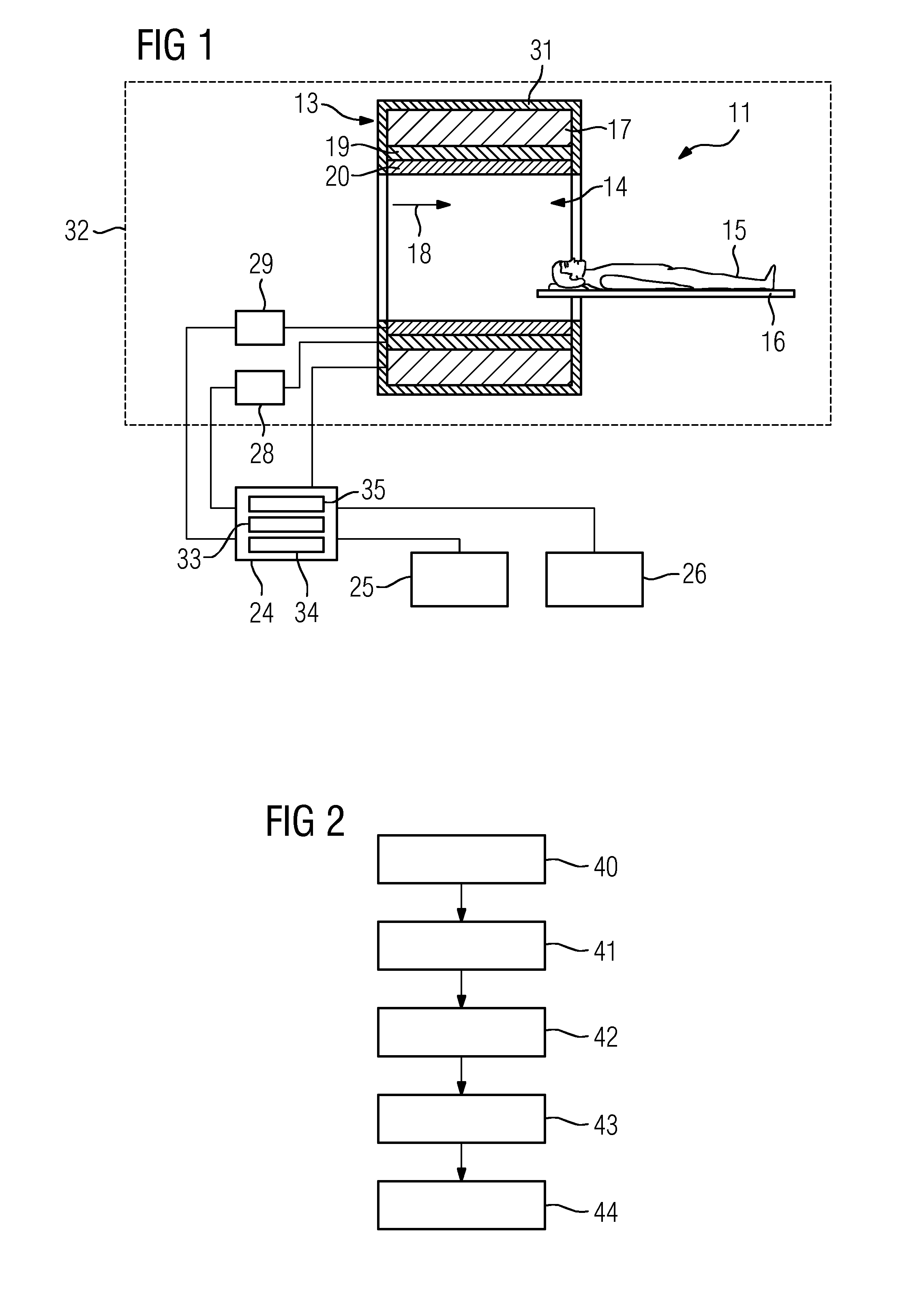
[0049]FIG. 2 shows a flow chart of an inventive method for determining a spatially resolved distribution of a marker substance which is located in an object under examination 15.

[0050]In a first method step 40, the signal acquisition unit 32 of the magnetic resonance device 11 acquires magnetic resonance signals of an examination region of the object under examination 15 by means of a quantitative magnetic resonance method. In a further method step 41, a quantification of a measurement-n-tuple of material parameters takes place with the aid of the acquired magnetic resonance signals by means of the quantification unit 33 of the computing unit 24. In a further method step 42, a comparison of the measurement-n-tuple with a known marker substance-n-tuple of the marker substance takes place by means of the comparison unit 34 of the computing unit 24. In a further method step 43, a calculation of a spatially resolved distribution of the marker substance in the examination region takes pl...

second embodiment

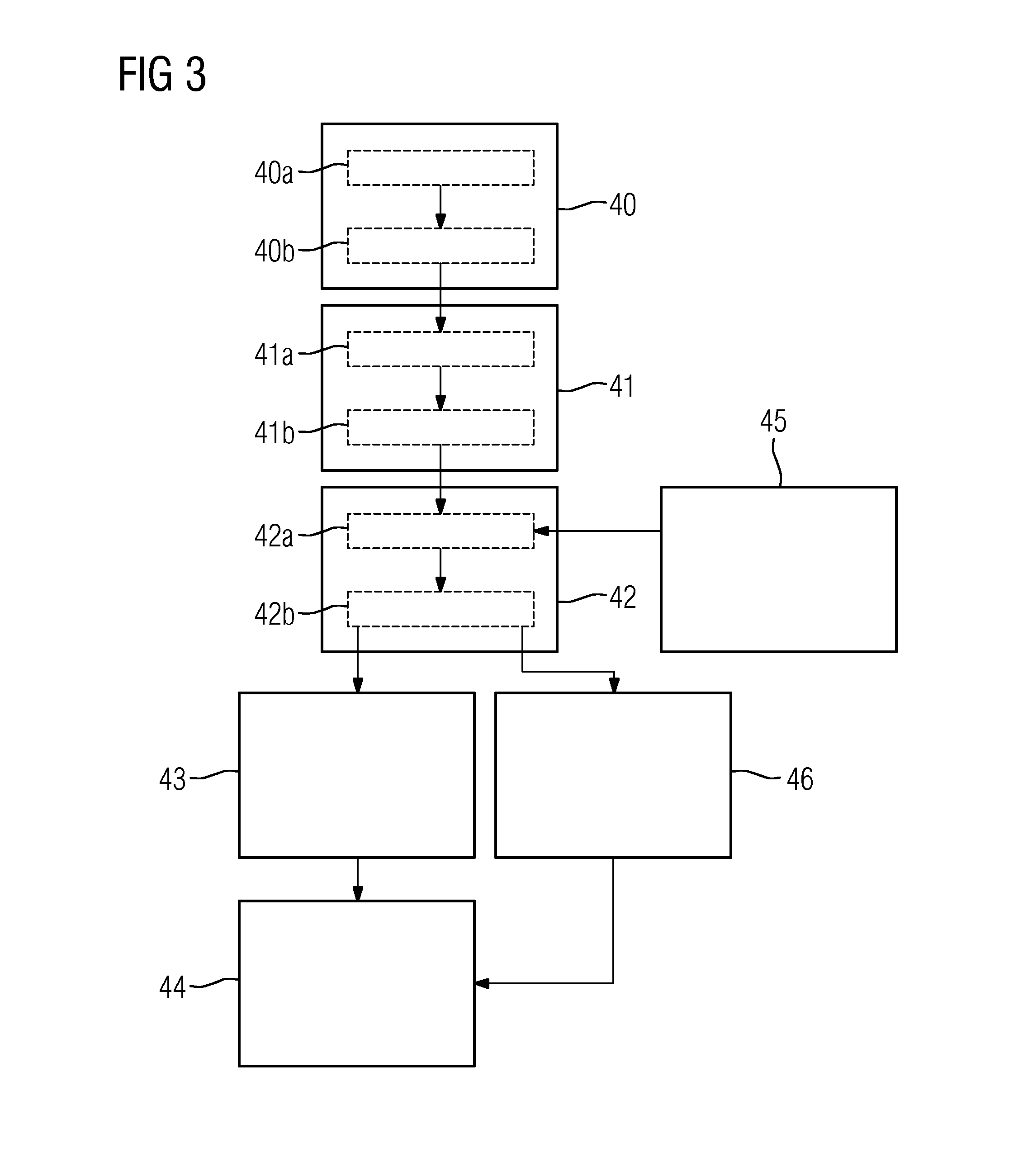
[0051]FIG. 3 shows a flow chart of an inventive method for determining a spatially resolved distribution of a marker substance which is located in an object under examination 15.

[0052]The following description is essentially restricted to the differences from the exemplary embodiment in FIG. 2 wherein, with regard to method steps which remain the same, reference is made to the description of the exemplary embodiment in FIG. 2. In principle, the same method steps are essentially identified with the same reference signs.

[0053]The second embodiment of the method according to the invention shown in FIG. 3 essentially comprises the method steps 40, 41, 42, 43 of the first embodiment of the method according to the invention as shown in FIG. 2. The second embodiment of the method according to the invention shown in FIG. 3 additionally comprises further method steps and sub-steps. Also conceivable is an alternative method sequence to that of FIG. 3 which has only part of the additional meth...


PUM


Abstract

A method for determining a spatially resolved distribution of a marker substance, a marker substance and a use of a marker substance in a quantitative magnetic resonance method is provided. To specify an effective possibility of determining a spatially resolved distribution of a marker substance in an object under examination, the method for determining a spatially resolved distribution of a marker substance, located in an object under examination, includes: acquiring magnetic resonance signals of an examination region of the object under examination by means of a quantitative magnetic resonance method, quantifying a measurement-n-tuple of material parameters with the aid of the acquired magnetic resonance signals, comparing the measurement-n-tuple with a known marker substance-n-tuple of the marker substance, calculating a spatially resolved distribution of the marker substance in the examination region with the aid of the result of the comparison, and providing the spatially resolved distribution of the marker substance.

Description

[0001]This application claims priority to DE 102014211695.3, having a filing date of Jun. 18, 2014, the entire contents of which are hereby incorporated by reference.FIELD OF TECHNOLOGY[0002]The following relates to a method for determining a spatially resolved distribution of a marker substance, a marker substance, and a use of a marker substance in a quantitative magnetic resonance method.BACKGROUND[0003]In a magnetic resonance device, also known as a magnetic resonance tomography system, the body of the subject to be examined, particularly that of a patient, is typically exposed to a relatively strong magnetic field of, for example, 1.5 or 3 or 7 Tesla, with the aid of a main magnet. In addition, gradient pulses are played out with the aid of a gradient coil unit. By means of a high frequency antenna unit, using suitable antenna devices, high frequency pulses, particularly excitation pulses, are transmitted, which leads to the nuclear spins of particular atoms being excited into ...

Claims


Application Information

Patent Timeline
Patent Type & Authority Applications(United States)
IPC IPC(8): A61B5/055
CPCA61B5/055G01R33/4828G01R33/50G01R33/5601
Inventor GRODZKI, DAVID
Owner SIEMENS AG
Why Eureka
Try Eureka