
Vehicle

a technology for vehicles and motors, applied in the field of vehicles, can solve the problems of reducing fuel efficiency, reducing electric power generation efficiency, and ineffective use of heat accumulated in solar panels, and achieve the effects of increasing fuel efficiency, effectively heating up the engine, and warming up the engin

Inactive Publication Date: 2015-12-17
TOYOTA JIDOSHA KK
View PDF17 Cites 5 Cited by
  • Summary
  • Abstract
  • Description
  • Claims
  • Application Information

AI Technical Summary

Benefits of technology

The present invention aims to quickly warm up an engine by using heat accumulated in a solar panel. It uses a temperature acquisition system to monitor the temperature of the engine coolant and the solar panel. An exchange control system is then used to control the operation of the engine-panel coolant exchange device based on the monitored temperatures. This allows for appropriate cooling of the solar panel and warming of the engine. The technical effect of the invention is to increase the efficiency of generating electric power from the solar panel.

Problems solved by technology

However, the solar panel (solar cell) faces such a problem that electric power generation efficiency decreases as the temperature increases.
However, the heat accumulated in the solar panel is not effectively used either on the solar car proposed in Japanese Patent Application Laid-open No.
Therefore, a part of a fuel is used for the warmup operation, which thus causes a decrease in fuel efficiency.
However, the heat is not effectively used on the same vehicle.

Method used


Image

  • Vehicle
  • Vehicle
  • Vehicle

Examples


Embodiment Construction

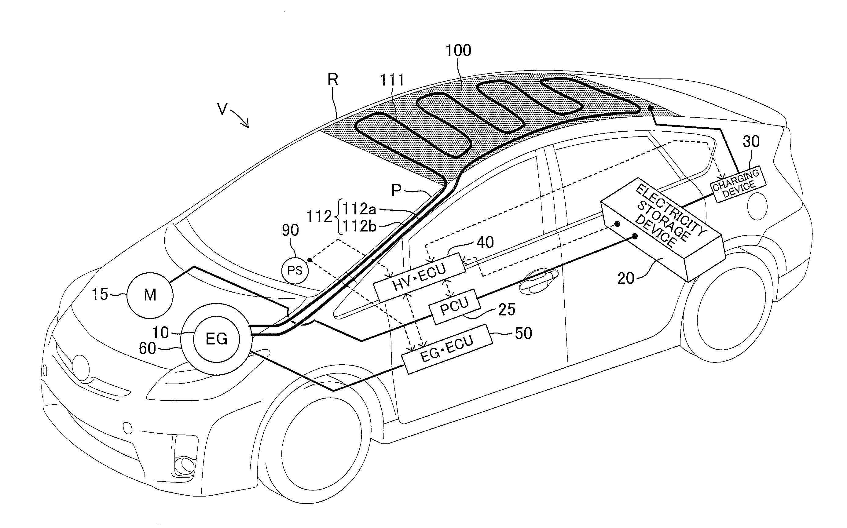
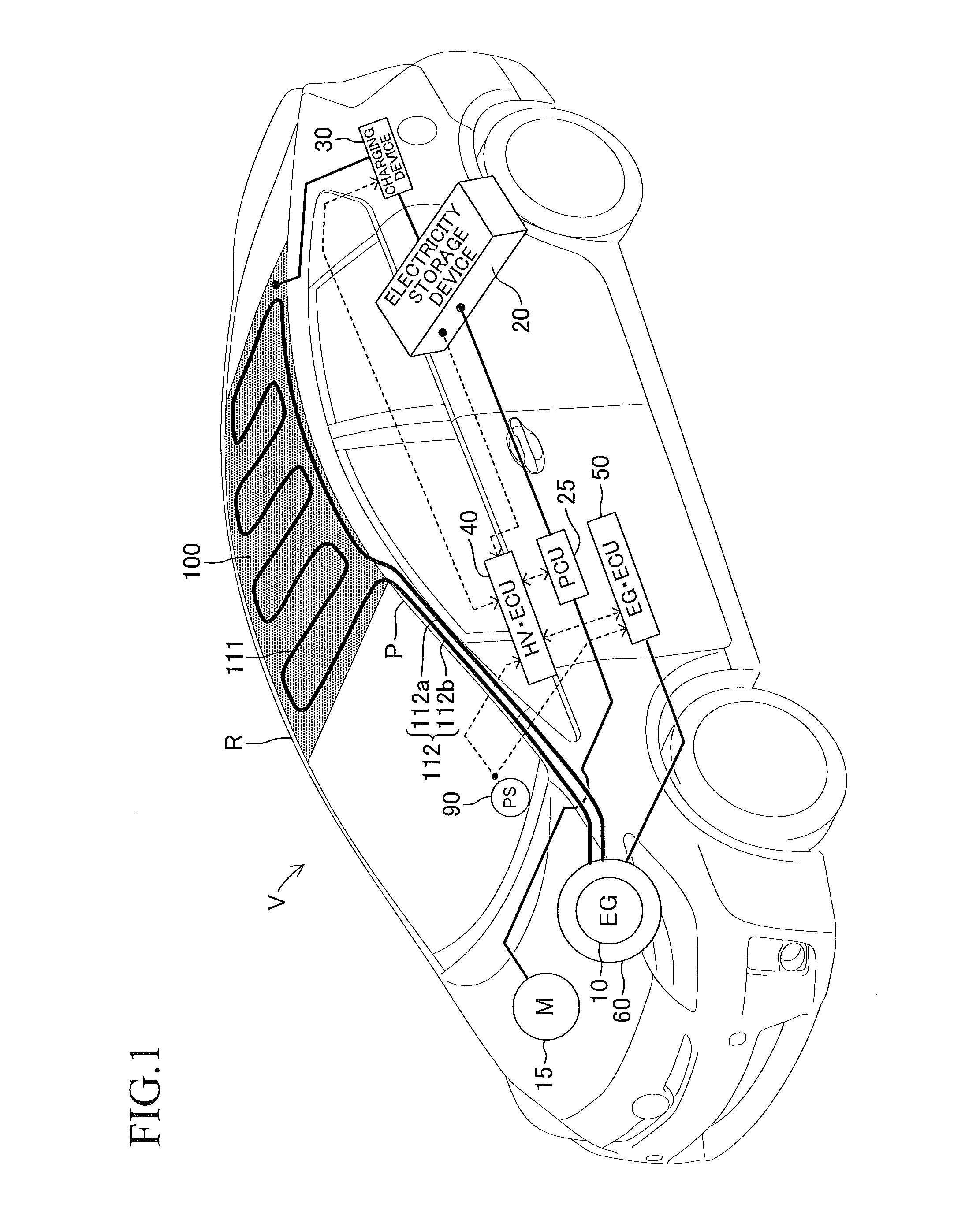
[0047]A description is now given of a vehicle according to an embodiment of the present invention referring to the drawings. FIG. 1 illustrates a schematic configuration of a vehicle V according to the embodiment.

[0048]The vehicle V according to this embodiment is a hybrid vehicle of a plug-in type including a hybrid system and a photovoltaic power generation system. The hybrid system includes an engine 10 and a motor 15 for generating a driving force for travel of the vehicle V, an electricity storage device 20, a power control unit 25, a charging device 30, a hybrid electronic control unit 40 (referred to as hybrid ECU 40), and an engine electronic control unit 50 (referred to as engine ECU 50).

[0049]The electricity storage device 20 includes a high voltage battery used as a drive power supply mainly for the motor 15, a low voltage battery used as a power supply for 12-V system in-vehicle loads, and an SOC sensor for detecting a state of charge (SOC) of each of the batteries. The ...


PUM


Abstract

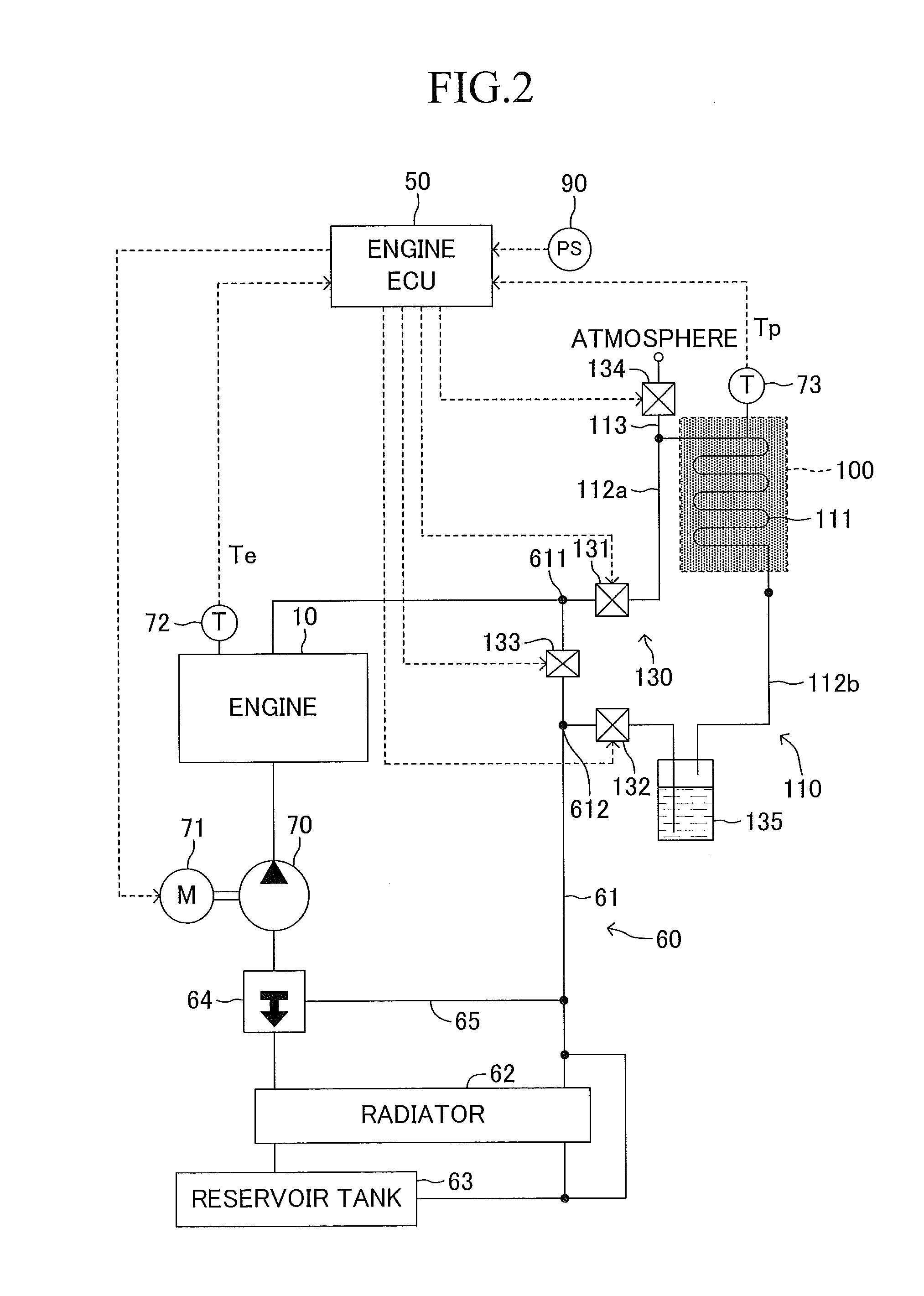
To increase electric power generation efficiency of a solar panel while effectively using heat accumulated in the solar panel, a panel-side pipe is installed on a rear surface of the solar panel. The panel-side pipe is connected to an engine coolant passage. When a power switch is in an OFF state, and an exchange condition for a coolant is satisfied, an engine ECU drives a water pump to circulate the coolant to the panel-side pipe. Consequently, the cool coolant accumulated in the engine coolant passage and the warmed coolant accumulated in the panel-side pipe are exchanged with each other. As a result, the solar panel is cooled, and the engine is warmed.

Description

BACKGROUND OF THE INVENTION[0001]1. Field of the Invention[0002]The present invention relates to a vehicle including a solar panel installed thereon.[0003]2. Description of the Related Art[0004]Hitherto, there has been known a vehicle including a solar panel on a roof, and being configured to use electric power generated by the solar panel to supply electric power to various loads.[0005]For example, an electric vehicle proposed in Japanese Patent Application Laid-open No. 2000-323185 includes a cooler for cooling a rechargeable battery serving as a drive power supply for the vehicle, and is configured to supply electric power for operating the cooler from a solar panel.SUMMARY OF THE INVENTION[0006]A user of a vehicle selects a location good in an insolation condition for parking the vehicle, thereby generating electric power from a solar panel as much as possible. However, the solar panel (solar cell) faces such a problem that electric power generation efficiency decreases as the t...

Claims


Application Information

Patent Timeline
Patent Type & Authority Applications(United States)
IPC IPC(8): B60K11/02B60L8/00
CPCB60K11/02Y10S903/903B60L8/003B60K2001/003B60K2016/003Y02T10/90Y02T10/7072
Inventor MAENO, SEIGEN
Owner TOYOTA JIDOSHA KK
Learn More