
Spring device for spring-mounting a functional unit of an electrical appliance, and method for influencing a spring device of this kind

a technology of functional units and springs, applied in the field of springs, can solve the problems of large spring-mounted mass, extreme vibration and mechanical loading of washing machines, and achieve the effects of reducing vibration during operation, minimizing mechanical loads, and reducing nois

Active Publication Date: 2020-11-24
E G O ELEKTRO GERAETEBAU GMBH
View PDF33 Cites 0 Cited by
  • Summary
  • Abstract
  • Description
  • Claims
  • Application Information

AI Technical Summary

Benefits of technology

The invention is a spring device and method for influencing it to reduce vibrations and minimize mechanical loads during operation. The spring device can be adjusted by a single or both options mentioned earlier. The advantages of changing the spring constant or spring properties and the coupling effect by warming up or heating include that it can be controlled quickly and without the need for complex apparatuses. The coupling means can be composed of a material with a memory effect, which allows for a quick and stable response to changes in temperature. The spring device can also be adjusted based on the presumption that certain frequencies or rotation speeds of the functional unit are approaching or have reached a resonant frequency. This approach allows for a quick identification of the resonant frequency and a corresponding adjustment of the spring device. The invention provides a solution for reducing resonance problems and minimizing noise and mechanical loads during operation.

Problems solved by technology

The reason for this is that, when the laundry drum rotates, in particular at high rotation speeds for spin-drying laundry contained therein, there may be an unbalance due to non-uniformly distributed laundry and this can lead to extreme vibrations and mechanical loading of the washing machine at high rotation speeds.
Therefore, the spring-mounted mass is relatively large.

Method used


Image

  • Spring device for spring-mounting a functional unit of an electrical appliance, and method for influencing a spring device of this kind
  • Spring device for spring-mounting a functional unit of an electrical appliance, and method for influencing a spring device of this kind

Examples


Embodiment Construction

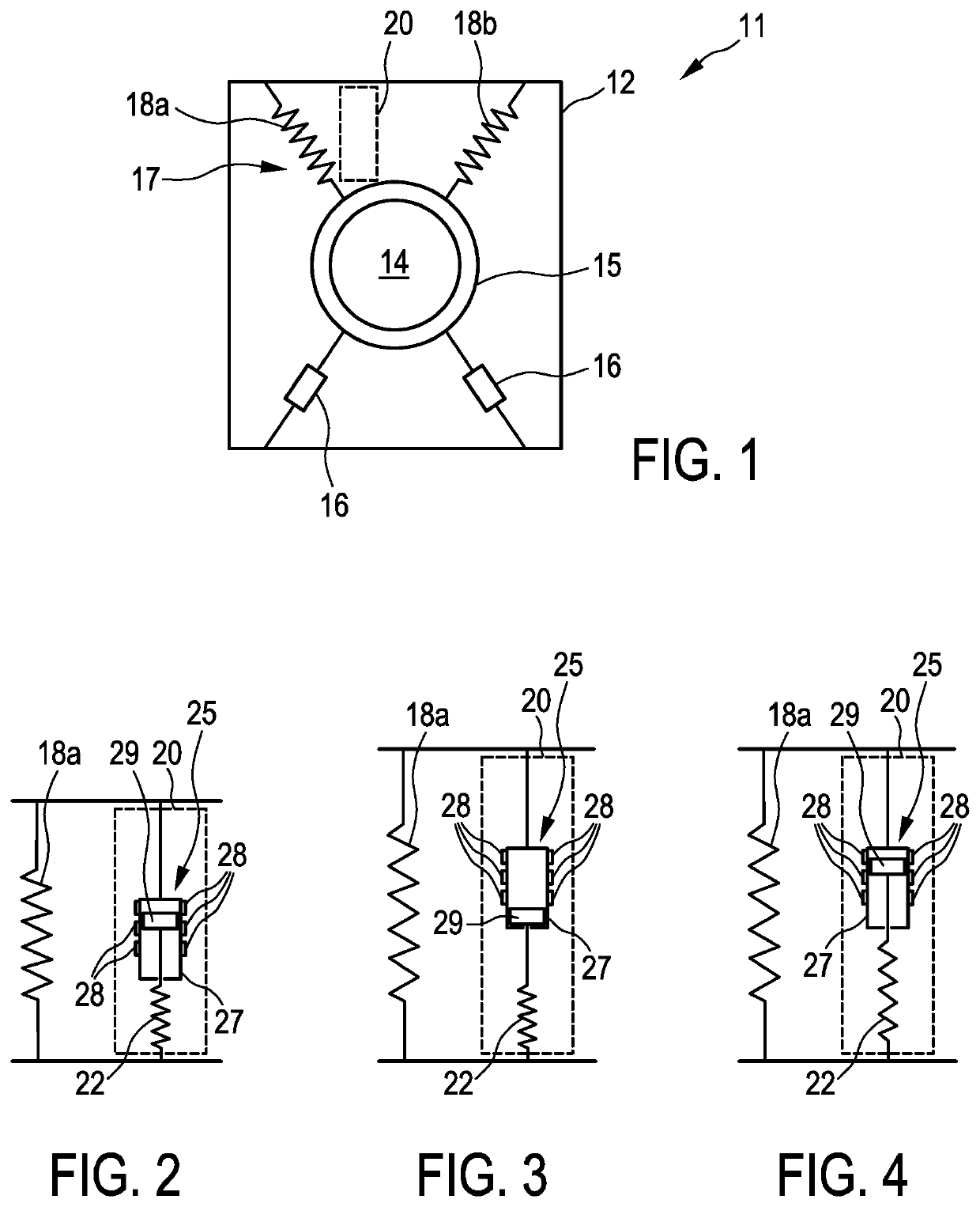
[0039]FIG. 1 illustrates a simplified view of a washing machine 11 comprising a housing 12. A laundry drum 14 is held, specifically such that it can rotate, in a manner which is known per se in a laundry drum holder 15 in the said housing. A drive motor, not illustrated here, is usually fitted to the laundry drum holder 15 in order to be able to rotate the laundry drum 14.

[0040]On account of the possible occurrence of an abovementioned unbalance during rotation of the laundry drum 14, in particular at high rotation speeds such as during spin-drying for example, conventional vibrations may occur in the washing machine 11, so that the said washing machine wobbles to a considerable extent. In order to be able to absorb the said vibrations to a certain extent, a spring device 17 is provided at the top of the laundry drum holder 15. The said spring device has two springs 18a and 18b, advantageously helical springs composed of metal. The said springs allow a certain degree of movement of ...


PUM


Abstract

A spring device for spring-mounting a laundry drum of a washing machine has at least one spring means and coupling means for coupling the spring means to the spring device. The spring means has a spring constant or spring properties which are temperature-dependent and can be varied by a temperature effect on the spring means. As an alternative or in addition, the coupling means are designed in a temperature-dependent manner in such a way that they vary their coupling effect between the spring means and the spring device by a temperature effect. Heating means are provided for the spring means and / or for the coupling means in order to warm up the said spring means and / or coupling means and to change their spring properties or their coupling effect. Therefore, the spring-mounting arrangement of the laundry drum can be thermally, and therefore quickly and simply, varied.

Description

CROSS-REFERENCE TO RELATED APPLICATIONS[0001]This application claims priority from German Application No. 10 2017 217 416.1, filed Sep. 29, 2017, the contents of which are hereby incorporated herein in its entirety by reference.BACKGROUND[0002]The invention relates to a spring device for suspending and / or for spring-mounting a functional unit of an electrical appliance, which functional unit, in particular, can be moved or is moved and is therefore subject to vibrations. In particular, this electrical appliance is a washing machine or a tumble dryer comprising a laundry drum which is suspended by the spring device not only in respect of its possible movements but also can be suspended from springs for spring-mounting purposes. The invention further relates to a method for influencing a spring device of this kind.[0003]In washing machines of the conventional type, a laundry drum is arranged in a drum receptacle and suspended with springs, generally from two springs at the top and ten...

Claims


Application Information

Patent Timeline
Patent Type & Authority Patents(United States)
IPC IPC(8): D06F37/22F16F1/12F16F15/06F16F15/027F16F3/04F16F15/067F16F15/023F16F15/02F16F13/00F16F1/04F16F9/02F16F1/02
CPCF16F15/022F16F15/067F16F15/06F16F1/121F16F9/0281F16F15/0232F16F1/041F16F3/04D06F37/22F16F9/029F16F13/002F16F15/0275F16F2224/0258F16F2224/0208F16F1/024F16F2222/02F16F2228/066F16F2230/0005
Inventor SCHAUMANN, UWE
Owner E G O ELEKTRO GERAETEBAU GMBH
Learn More