
System, Method and Computer Program Product For Photometric System Design and Environmental Ruggedization

a photometric system and environmental ruggedization technology, applied in the field of photometric system design, can solve the problems of inability to automate disadvantages of conventional photometric system design approaches, and inability to apply global optimization and conditional optimization for specific applications. the functionality of conventional software is also limited to relate selection optimization and environmental factors

Active Publication Date: 2015-12-10
HALLIBURTON ENERGY SERVICES INC
View PDF4 Cites 25 Cited by
  • Summary
  • Abstract
  • Description
  • Claims
  • Application Information

AI Technical Summary

Benefits of technology

The present invention relates to a method for designing and optimizing photometric systems, which are used in the oil and gas industry for optical sensing applications. The invention uses genetic algorithms to optimize the design of optical elements and determine the number of actual optical elements needed for system implementation. The invention also includes environmental ruggedization of the system to ensure functionality and reliability in the harsh environments in which the photometric systems will be deployed. The technical effects of the invention include improved accuracy and efficiency of photometric system design and optimization, as well as enhanced reliability and functionality of the system components.

Problems solved by technology

Conventional photometric system design approaches are disadvantageous for a variety of reasons.
However, the existing software is designed for general purpose use, and does not automate global optimization and conditional optimization for specific application in photometric system design.
The conventional software also has very limited functionality to relate selection optimization with environmental factors, such as, for example, the downhole environment in which the photometric system will be deployed.

Method used


Image

  • System, Method and Computer Program Product For Photometric System Design and Environmental Ruggedization
  • System, Method and Computer Program Product For Photometric System Design and Environmental Ruggedization
  • System, Method and Computer Program Product For Photometric System Design and Environmental Ruggedization

Examples


Embodiment Construction

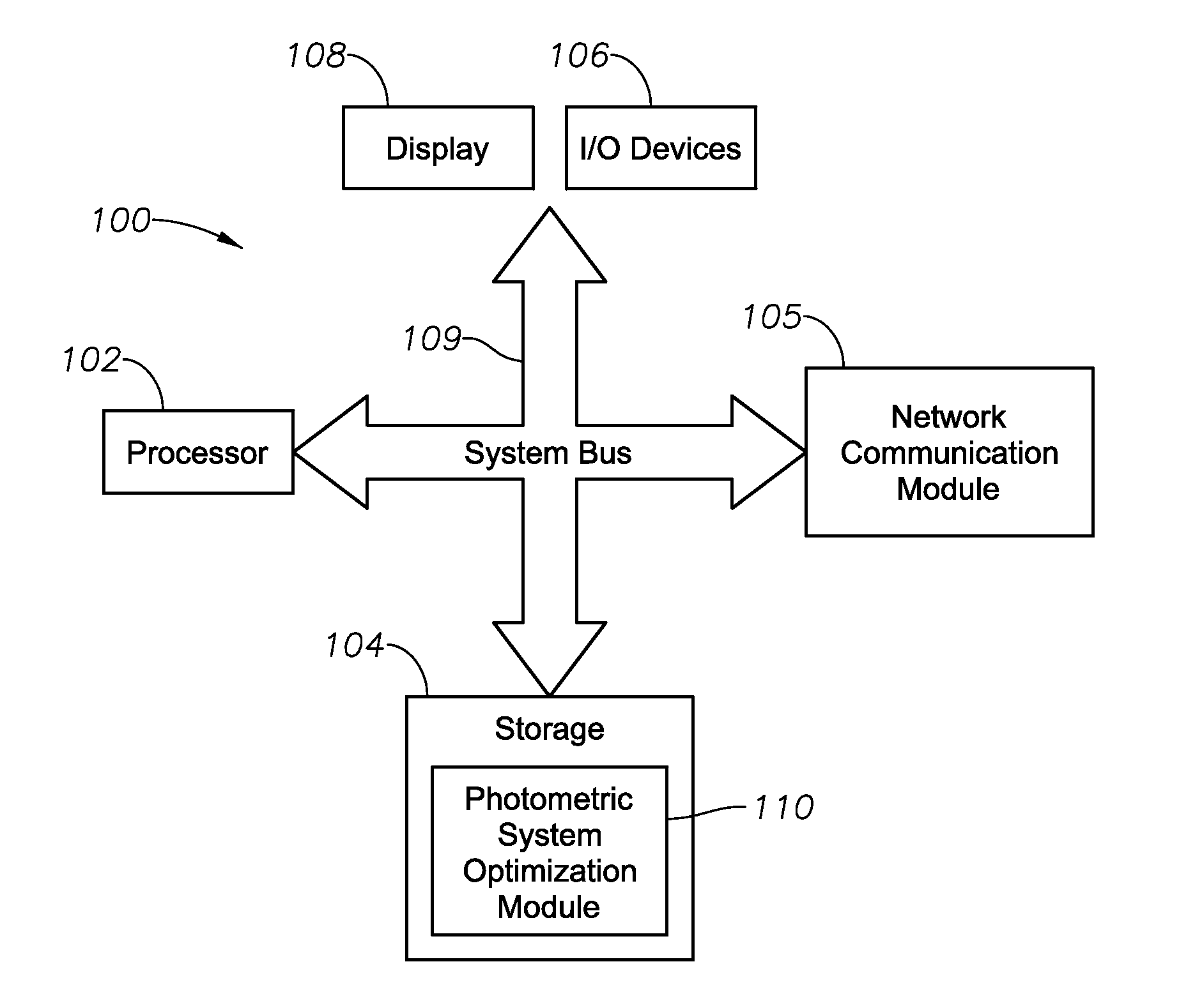
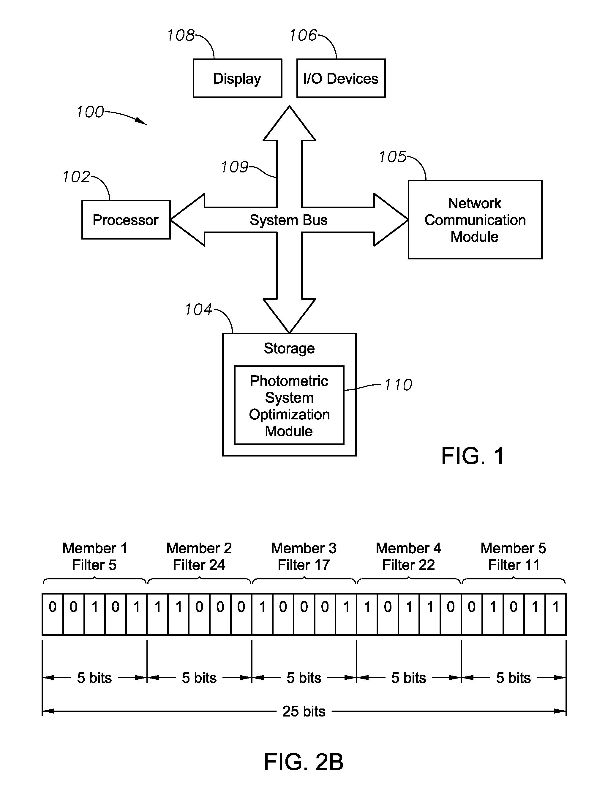
[0012]Illustrative embodiments and related methodologies of the present invention are described below as they might be employed in a method for photometric system design and environmental ruggedization. In the interest of clarity, not all features of an actual implementation or methodology are described in this specification. It will of course be appreciated that in the development of any such actual embodiment, numerous implementation-specific decisions must be made to achieve the developers' specific goals, such as compliance with system-related and business-related constraints, which will vary from one implementation to another. Moreover, it will be appreciated that such a development effort might be complex and time-consuming, but would nevertheless be a routine undertaking for those of ordinary skill in the art having the benefit of this disclosure. Further aspects and advantages of the various embodiments and related methodologies of the invention will become apparent from con...


PUM


Abstract

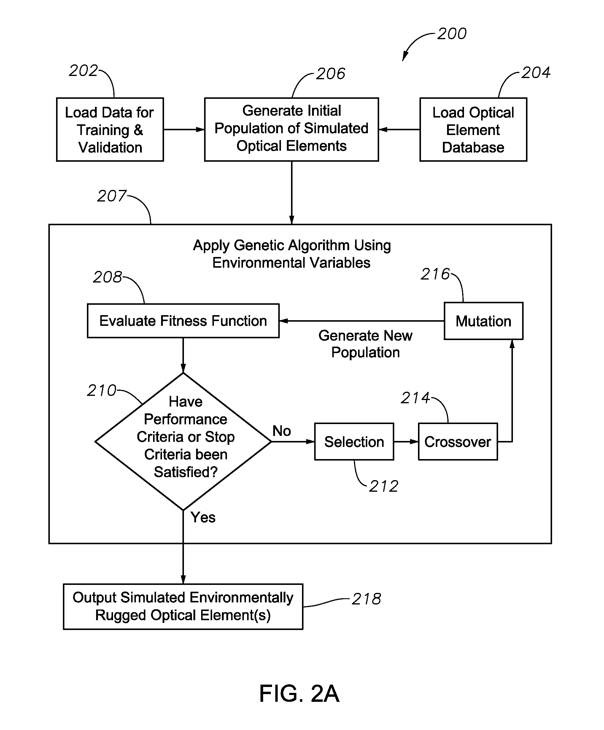
A photometric system design methodology employs genetic algorithms to optimize the selection of optical elements for inclusion in the photometric system in order to improve system performance with respect to environmental conditions (i.e., to “ruggedize” the photometric system). The genetic algorithms utilize a multi-objective fitness function to evolve simulated optical element selection, which may be a combination of optical filters and integrated computational elements. The system may also output a size reduced database that serve as simulated candidate optical elements through global optimization, or may output a fixed number of simulated optical elements through conditional optimization for actual tool implementation and calibration analysis

Description

FIELD OF THE INVENTION[0001]The present invention relates generally to designing photometric systems and, more specifically, to a system that utilizes genetic algorithms to optimize the design of an environmentally robust photometric system through computer simulation of candidate optical elements.BACKGROUND[0002]In recent years, optical computing techniques have been developed for applications in the Oil and Gas Industry in the form of optical sensors on downhole or surface equipment to evaluate a variety of fluid properties. An optical computing device, also referred to herein as photometric system, is a device configured to receive an input of electromagnetic radiation from a substance or sample of the substance and produce an output of electromagnetic radiation from a processing element, also referred to as an optical element. The optical element may be, for example, a narrow band optical filter or an Integrated Computational Element (“ICE”) (also known as a Multivariate Optical...

Claims


Application Information

Patent Timeline
Patent Type & Authority Applications(United States)
IPC IPC(8): G02B27/00G06N3/12G06V10/88
CPCG06N3/126G02B27/0012G06V10/94G06V10/88G06F18/2111
Inventor SHEN, JINGJONES, CHRISTOPHER MICHAELCHEN, DINGDINGZHANG, WEIPERKINS, DAVID L.
Owner HALLIBURTON ENERGY SERVICES INC
Learn More