
Rotating scattering plane based nonlinear optical spectrometer to study the crystallographic and electronic symmetries of crystals

a nonlinear optical spectrometer and scattering plane technology, applied in the direction of instruments, specific gravity measurement, counting objects on conveyors, etc., can solve the problems of insufficient number, inability to accurately assign symmetry, and inability to use pattern, etc., to achieve the effect of optimizing the fringe contras

Inactive Publication Date: 2015-12-10
CALIFORNIA INST OF TECH
View PDF11 Cites 11 Cited by
  • Summary
  • Abstract
  • Description
  • Claims
  • Application Information

AI Technical Summary

Benefits of technology

The present invention is a novel spectrometer that can measure a variety of materials, including those with strong correlations between electrons. The setup allows for measurements to be taken in cryostats and under different magnetic or strain fields. This means that complex electronic phases can be characterized in these materials. Overall, the invention offers a more versatility and flexibility for studying electronic properties.

Problems solved by technology

However, an accurate symmetry assignment, which relies on being able to perform a unique fit to a diffraction pattern, is not always possible.
Technical obstacles include not having a sufficient number of Bragg peaks owing to a finite instrument momentum range; spurious peaks arising from multiple scattering events, parasitic phases or microscopic domains in a crystal; the presence of elements with strong absorption or weak scattering cross-sections; and the unavailability of large single crystals comparable with the probe beam size.
However, several technical challenges associated with maintaining precise optical alignment from a rotating sample have so far precluded such experiments from being performed on small bulk single crystals and under extreme sample environments such as ultra low temperature, high magnetic field, or externally imposed strain.

Method used


Image

  • Rotating scattering plane based nonlinear optical spectrometer to study the crystallographic and electronic symmetries of crystals
  • Rotating scattering plane based nonlinear optical spectrometer to study the crystallographic and electronic symmetries of crystals
  • Rotating scattering plane based nonlinear optical spectrometer to study the crystallographic and electronic symmetries of crystals

Examples


embodiment

[0101]Scanning Embodiment

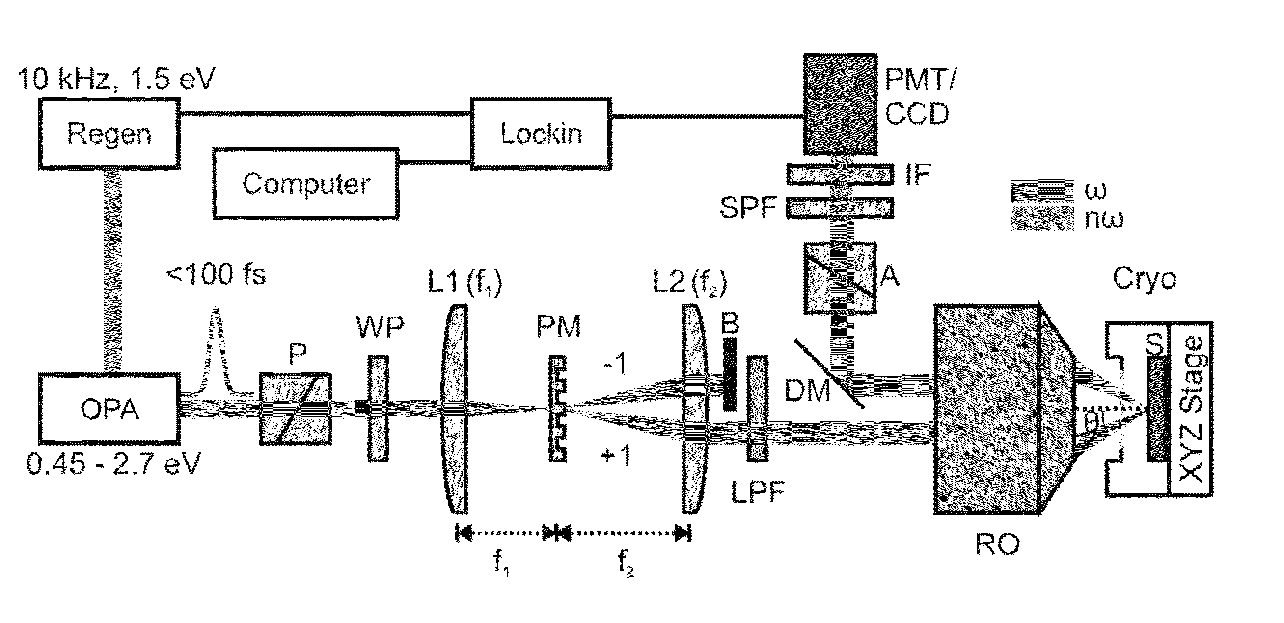
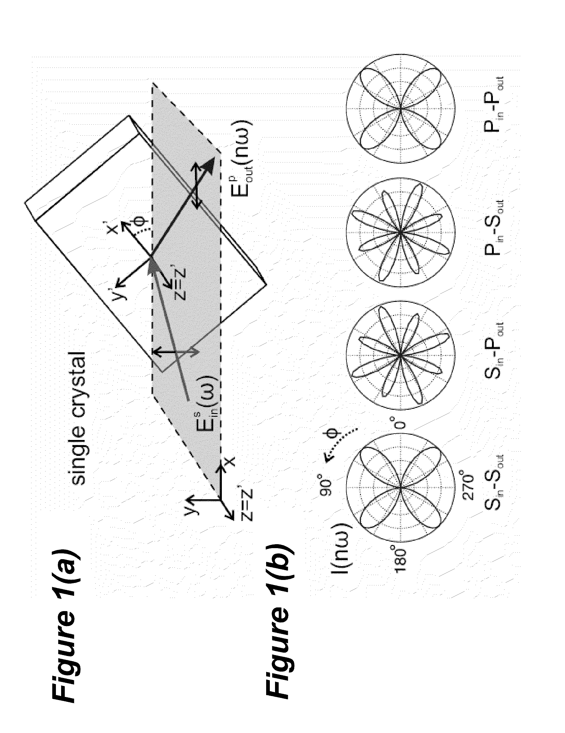
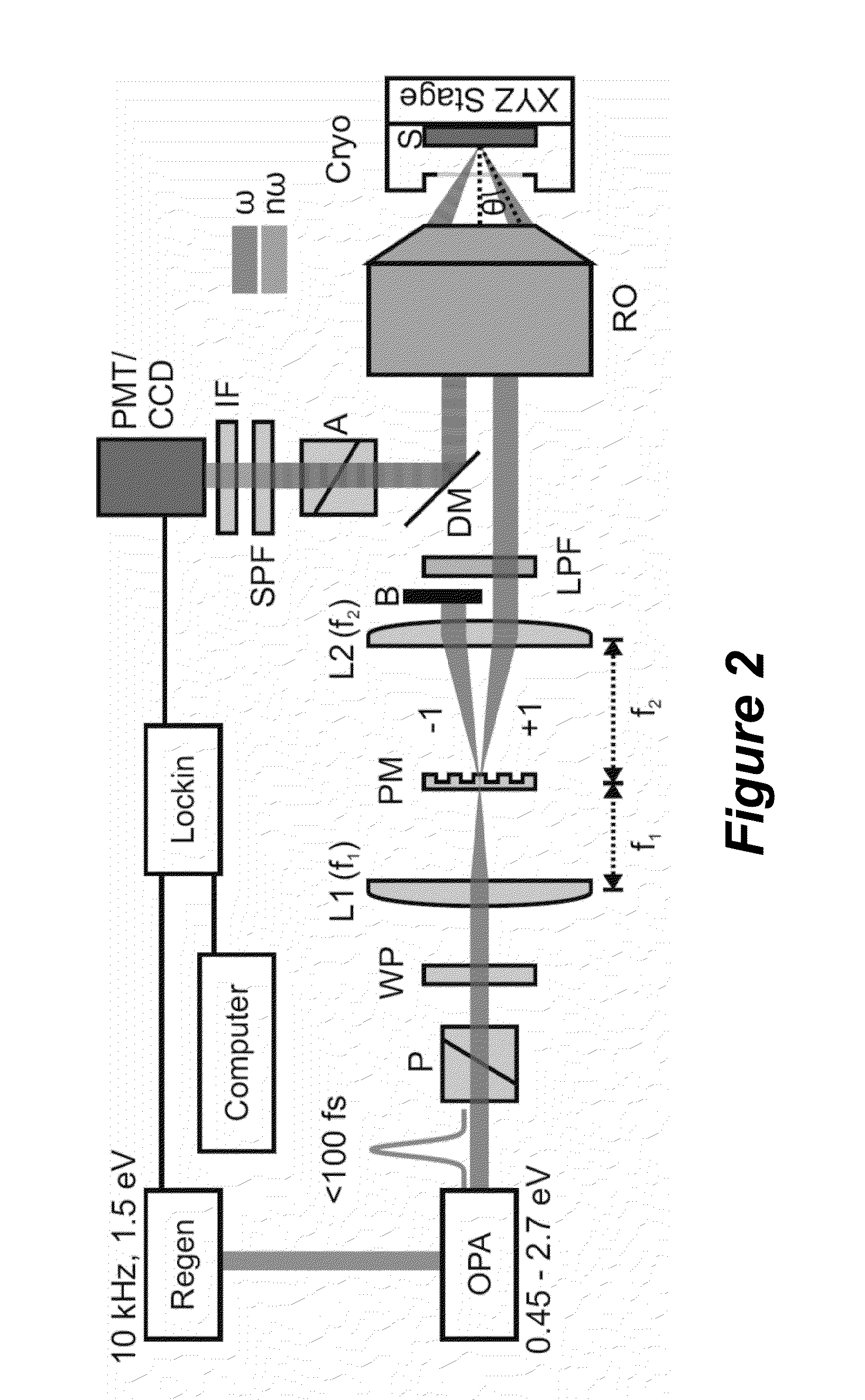
[0102]FIG. 11A-D illustrate performance using the apparatus in FIG. 2 in a scanning experiment (20 μm resolution), on a Sr2IrO4 sample, wherein FIG. 11A illustrates the RO illuminating the sample comprising Sr2IrO4 and the configuration of the Ir, Sr, and O atoms, FIG. 11B is a photograph of the sample, FIG. 11C plots representative NHG-RA measurements on the Sr2IrO4 for 30 regions that were tested, showing all results were identical without even the need to normalize, and FIG. 11D illustrates the locations / regions where the data in FIG. 11 C was taken.

[0103]Further Data

[0104]FIG. 12 illustrates second harmonic data taken for the Sr2IrO4 sample.

[0105]Process Steps

[0106]Irradiation Method

[0107]FIG. 13 illustrates a method for measuring Electromagnetic (EM) radiation scattered by a material, according to one or more embodiments of the invention. For example, the method can be a method of performing a nonlinear harmonic generation rotational anisotropy (NH-GRA)...


PUM

PropertyMeasurementUnit
diameteraaaaaaaaaa
diameteraaaaaaaaaa
wavelengthaaaaaaaaaa

Abstract

A method for measuring nonlinear Electromagnetic (EM) radiation emitted by a material, comprising rotating a beam of EM radiation to form a rotating beam; irradiating a surface of a material with the rotating beam at an oblique angle with respect to the surface, wherein the rotating irradiates a plurality of scattering planes in the material; and detecting nonlinear radiation emitted by the material in response to the rotating beam, such that the nonlinear radiation generated by each of the scattering planes is detected by the detector. This method opens the possibility of applying nonlinear optics as a probe of lattice and electronic symmetries on small bulk single crystals in ultra low temperature, high magnetic field or high pressure environments, which can greatly complement diffraction based techniques.

Description

CROSS REFERENCE TO RELATED APPLICATIONS[0001]This application claims the benefit under 35 U.S.C. Section 119(e) of co-pending and commonly-assigned U.S. Provisional Patent Application Ser. No. 61 / 989,056, filed on May 6, 2014, by David Hsieh and Darius H. Torchinsky, entitled “ROTATING SCATTERING PLANE BASED NONLINEAR OPTICAL SPECTROMETER TO STUDY THE CRYSTALLOGRAPHIC AND ELECTRONIC SYMMETRIES OF CRYSTALS,” attorneys' docket number 176.107-US-P1 (CIT-6892-P), which application is incorporated by reference herein.STATEMENT REGARDING FEDERALLY SPONSORED RESEARCH AND DEVELOPMENT[0002]This invention was made with government support under W911NF-13-0059 and W911NF-13-1-0293 awarded by the Army Research Office. The government has certain rights in the invention.BACKGROUND OF THE INVENTION[0003]1. Field of the Invention[0004]This invention relates to a method and apparatus for measuring nonlinear Electromagnetic radiation emitted by a material.[0005]2. Description of the Related Art[0006]...

Claims


Application Information

Patent Timeline
Patent Type & Authority Applications(United States)
IPC IPC(8): G01N21/84G02F1/37G01N21/47G02F1/355
CPCG01N21/84G02F1/3551G02F1/37Y10T29/49771G01N2021/4709G01N2021/8477G01N21/4788G01N21/636
Inventor HSIEH, DAVIDTORCHINSKY, DARIUS H.
Owner CALIFORNIA INST OF TECH
Learn More