
Enhanced vortex fluid treatment apparatus, system, and method for separating solids from solids-containing liquids

a technology of vortex fluid and treatment apparatus, applied in the direction of gravity filter, centrifugal force sediment separation, feed/discharge of settling tank, etc., can solve the problems of reducing the overall efficiency of the entire settling tank, labor and time-consuming, and the physical shape of rectangular settling compartments

Active Publication Date: 2015-12-03
AMARILLO EQUITIES
View PDF13 Cites 3 Cited by
  • Summary
  • Abstract
  • Description
  • Claims
  • Application Information

AI Technical Summary

Benefits of technology

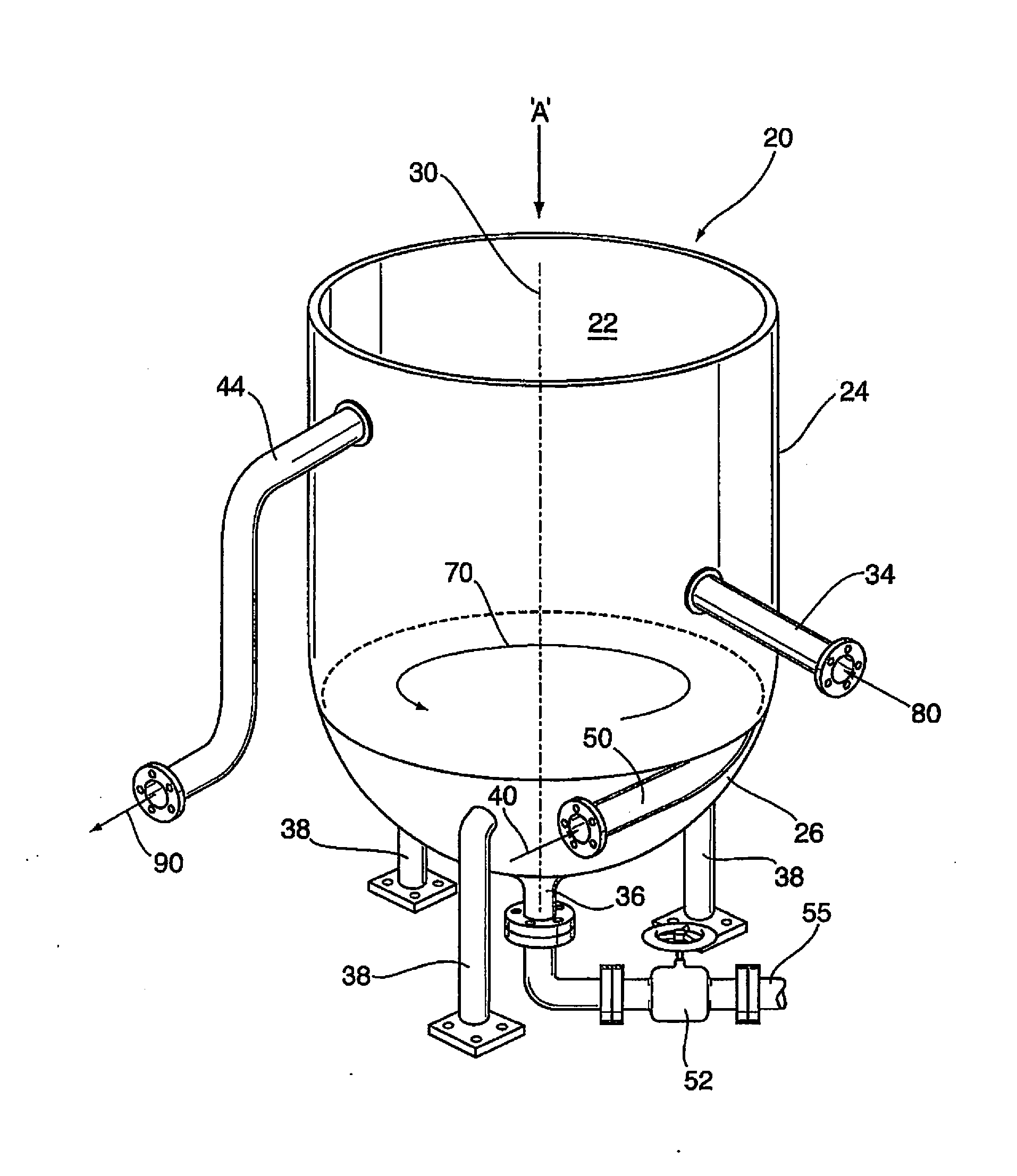
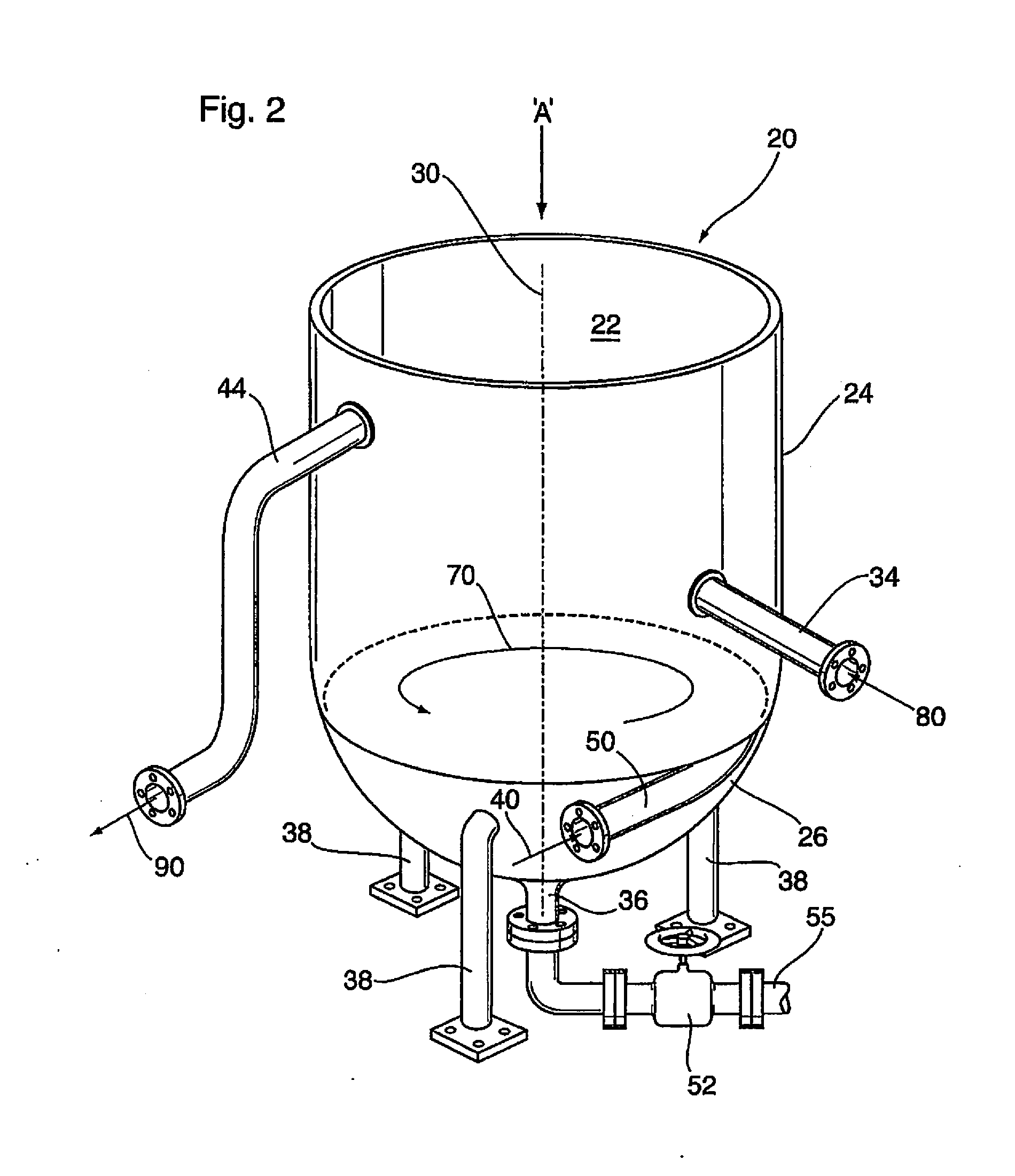
The present invention provides a new kind of settling tank that has a special bottom shape that helps keep solids from buildup and requires no mechanical rake to remove them. The tank has a rotating vortex that helps to remove solids from the bottom of the tank. This improvement prevents solid buildup in the tank and ensures better tank performance.

Problems solved by technology

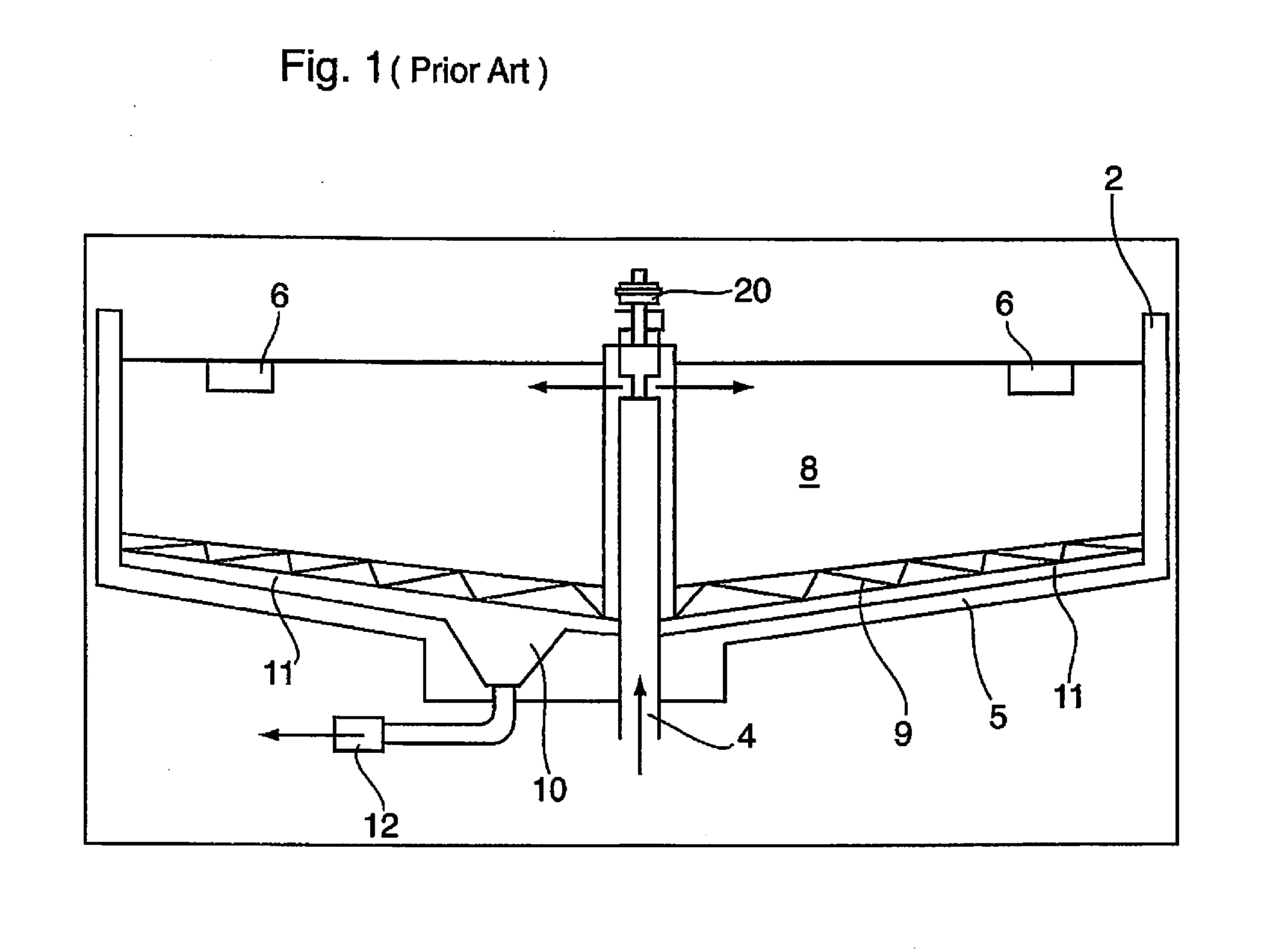
The physical shape of such rectangular settling compartments present a number of inefficiencies.
The deposition of the solids in these corners effectively reduces the working volume of the chamber or compartment and thus reduces the overall efficiency of the entire settling tank.
Furthermore, as these solids collect, the weight of successive solids collecting on top of other solids compresses these settled solids making their removal, labor and time intensive.
Further compounding the ineffectiveness of the rectangular compartments is the addition of suction lines and other internal plumbing that also creates traps, hampering the effectiveness of the settling.
The rectangular shape of the design and the presence of internal plumbing, however, creates the potential for traps and solids collection.
All clarifying / settlement tanks, including rectangular systems, used for separating solids from solids-containing liquids, will typically have the problem, after operation of a period of time, of build-up of precipitated solids on the bottom of the tank.
Such build-up, if permitted to continue, detrimentally reduces the volume of the settling tank and thus the tank's speed and capacity to clarify and separate solids from quantities of solids-containing liquids.
Thus having to stop such continuous operation for removal of solids from the bottom of the tank is not only time consuming and labour intensive, but further causes complete cessation of all upstream supply of solids-containing fluids until the precipitated solids have been removed from the tank and the tank brought back into operation.
Such additional processing capacity, and operation of the units in a “staggered manner”, adds greater capital cost and expense.
An alternative known manner and apparatus for allowing removal of sediment from settlement tanks but allowing for continued clarification of fluids in the tanks, but which adds considerable cost and mechanical complexity, is to provide a frusto-conical base and a rotating mechanical arm or arms (“rakes”) which continually “sweeps” the frusto-conical interior surface of any settled sediment and continually directs such sediment downwardly into a solids outlet, situated centrally and co-axially within the frusto-conical surface.

Method used


Image

  • Enhanced vortex fluid treatment apparatus, system, and method for separating solids from solids-containing liquids
  • Enhanced vortex fluid treatment apparatus, system, and method for separating solids from solids-containing liquids
  • Enhanced vortex fluid treatment apparatus, system, and method for separating solids from solids-containing liquids

Examples


example 1

Natural Vortex

[0150]The natural vortex created in a cylindrical compartment of the exemplary system was observed for comparison with systems comprising a jetting fluid stream of the present invention.

Method and Materials—Cylindrical Compartment

[0151]The cylindrical compartment having a six (6) foot diameter cylinder shape and torispherical bottom was used. A six (6) inch diameter drain was located in the center of the cylindrical compartment with a manually actuated compression valve to shut off flow to the drain (FIG. 11).

[0152]The cylindrical compartment was completely filled with fluid, in this case water, as it would be in actual field operations to a depth of 4 ft above that portion of the cylindrical vessel that transitions to a torisherical bottom. The compartment was allowed to stand idle for twelve (12) hours prior to the test to allow earth gravitational forces to stabilize.

[0153]There were significant amounts of settled solids collected on the bottom of the compartment. T...

example 2

Top-Located Vertical Jetting Stream

[0156]A second test was conducted utilizing a cylindrical compartment in combination with a jetting fluid stream of approximately ½″ diameter via a ½ inch diameter garden hose, introduced in a direction parallel to the longitudinal axis of the cylindrical portion of the compartment above the top fluid level of the contained fluid, at an velocity of approximately 130 ft. / min. (i.e. 20 l / min×0.0353147 cu.ft / l / (Π×(0.5 / 12)2)=130 ft / min). The effect of the jetting fluid stream on the natural vortex observed in Example 1 was determined.

Method and Materials—Cylindrical Compartment

[0157]A second cylindrical compartment identical to the compartment used in Example 1 was used. As in Example 1, the cylindrical compartment had a six (6) foot cylinder shape and torispherical bottom. A six (6) inch diameter drain was located in the center of the cylindrical compartment with a manually actuated compression valve to shut off flow to the drain.

[0158]As in Example 1...

example 3

Bottom-Located Horizontal Jetting Stream

[0161]The effect of a jetting stream introduced in essentially the same direction as the naturally occurring vortex was tested and compared to the observations made in Examples 1 and 2.

Method and Materials—Cylindrical Compartment

[0162]A third cylindrical compartment identical to the preceding Examples was used. Significant settled solids were again evident on the bottom of the settling compartment after the 12 hour stabilization period. The fluid was then allowed to gravity drain via the center drain outlet in a similar fashion as in the previous two tests.

[0163]For this third test, the forty (40) psi, twenty (20) liter per minute (130 ft / min) jetting stream was introduced in the lower portion of the chamber, well below the top of the torispherical section, essentially at the bottom of the torispherical bottom but located adjacent to the outer tank wall furthest from the center drain (FIG. 13). By introducing the jetting stream along the botto...


PUM

PropertyMeasurementUnit
diameteraaaaaaaaaa
diameteraaaaaaaaaa
diameteraaaaaaaaaa

Abstract

A settling tank apparatus for removing solids from a solids-containing fluid, having a vertical cylindrical portion and a bottom portion having a downwardly-extending substantially torispherical, ellipsoidal, hemispherical or frusto-conical shaped curved interior surface. A jetting fluid source is provided in a lower region of the tank, preferably in the bottom of the tank, which directs a jetting fluid in a tangential direction in a plane substantially perpendicular to said longitudinal axis of the tank, to enhance rotational swirling of a created vortex in the bottom of tank when solids are drained therefrom, to thereby reduce deposition and build up of settled solids on the curved interior of the bottom of the tank. A system incorporating a plurality of tanks of such design and a method for removing solids from a solids-containing fluid using a tank of such design, is further disclosed.

Description

FIELD OF THE INVENTION[0001]The present invention relates to settling or clarification tanks for treating fluids, and more particularly treating contaminated fluids including water, and more particularly relates to a novel settling tank, a system of settling tanks having novel features, and a method of operating a settling tank or tanks having such features, all for treating and removing solids from solids-containing liquids.BACKGROUND OF THE INVENTION AND DESCRIPTION OF PRIOR ART[0002]Clarification tanks (aka settlement tanks) are used in a variety of applications, including removal of solids from sewage and removal of drill tailings and heavier-than water compounds present in drilling fluids to permit recycled use of water that may be present in such drilling fluids.[0003]A common design for fluid settling systems is the use of rectangular vessels that are segmented into a series of smaller compartments by dividers or weirs that restrict the forward movement of the fluids being ci...

Claims


Application Information

Patent Timeline
Patent Type & Authority Applications(United States)
IPC IPC(8): B01D21/24C02F1/00
CPCB01D21/2411C02F2001/007C02F1/00B01D21/2472C02F2301/024C02F2301/026C02F2301/046B01D21/26
Inventor SMITH, DONALD R.
Owner AMARILLO EQUITIES
Learn More