
Computer cooling system and method for cooling

a computer and cooling system technology, applied in the direction of electrical apparatus contruction details, compression machines with non-reversible cycles, light and heating apparatus, etc., can solve the problems of increasing operational costs, increasing energy consumption of air conditioning units, and relatively inefficient, so as to achieve the effect of increasing pressure and temperatur

Inactive Publication Date: 2015-11-19
PSH ENERGIA
View PDF3 Cites 9 Cited by
  • Summary
  • Abstract
  • Description
  • Claims
  • Application Information

AI Technical Summary

Benefits of technology

The present invention is about a cooling system for servers installed in Data Centers. It uses a refrigerant fluid and a compressor to absorb the heat generated by the server and release it to the exterior. The system has an evaporator, a condenser, an expansion valve, and a compressor. The system controls the temperature of the refrigerant to prevent the air from dropping below the dew point and ensures that there is no condensation of water in the Data Center. The technical effects of the invention are improved cooling efficiency, reduced energy consumption, and prevention of damage to server components due to overheating.

Problems solved by technology

In any case, such air conditioning units demand great amounts of energy and are relatively inefficient, increasing operational costs.
In many cases, cooling systems consume an equal amount, if not more, than the electronic equipment themselves that they cool.
They may be used in many cases but a number of problems are associated with them.
For example, the “air economizers” that use air from the exterior have problems related to the quality of the air, introducing corrosives, dirt or dust.
It is also difficult to control the relative humidity.
In turn, the “water economizers” have problems associated with the presence of water in the Date Processing Center rooms due to the possibility of leaks that affect the electronic equipment.
There are also problems of freezing in Towers during winter time as well as a considerable consumption of water.
These systems have the inherent drawbacks of the low density solution of the water used in the previously mentioned data rooms.
In addition, these solutions are not very efficient because the cooling circuit has a great difference between the condensation temperature and evaporation temperature together with the losses in the heat exchange between the primary and secondary circuits.
Another great disadvantage is the appearance of condensed water in the evaporator, in the Data Processing Control room, when refrigerant temperatures below the dew point are used.

Method used


Image

  • Computer cooling system and method for cooling
  • Computer cooling system and method for cooling

Examples


Embodiment Construction

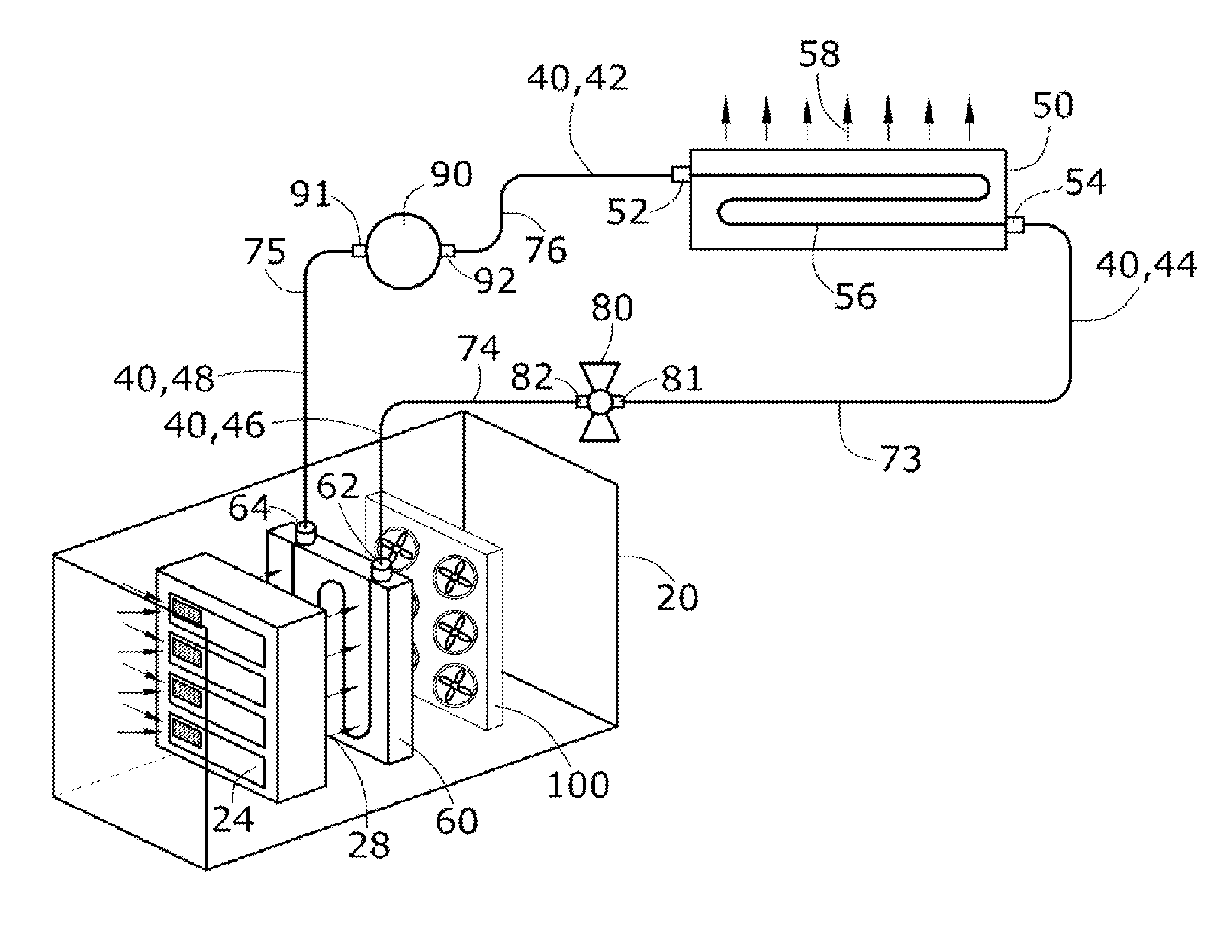
[0014]The cooling system for servers according to an arrangement of the present invention comprises:[0015]An evaporator that has an inlet and outlet. The evaporator is in thermal communication with a server to be cooled in a way that the evaporator absorbs the heat generated by the server.[0016]A compressor[0017]A condenser[0018]An expansion valve

[0019]Wherein the outlet of the evaporator is connected by a conduit to the inlet of the compressor, the outlet of the compressor is connected to the inlet of the condenser, and the outlet of the latter is connected to the inlet of the expansion valve and its outlet with the inlet of the evaporator, all connections being made by means of a conduit or tube.

[0020]The refrigerant fluid absorbs the heat generated by the server in the evaporator, changing phase from liquid to gas. Upon passing through the compressor, the refrigerant increases in pressure and temperature. Subsequently, the refrigerant circulates through the condenser and releases...


PUM


Abstract

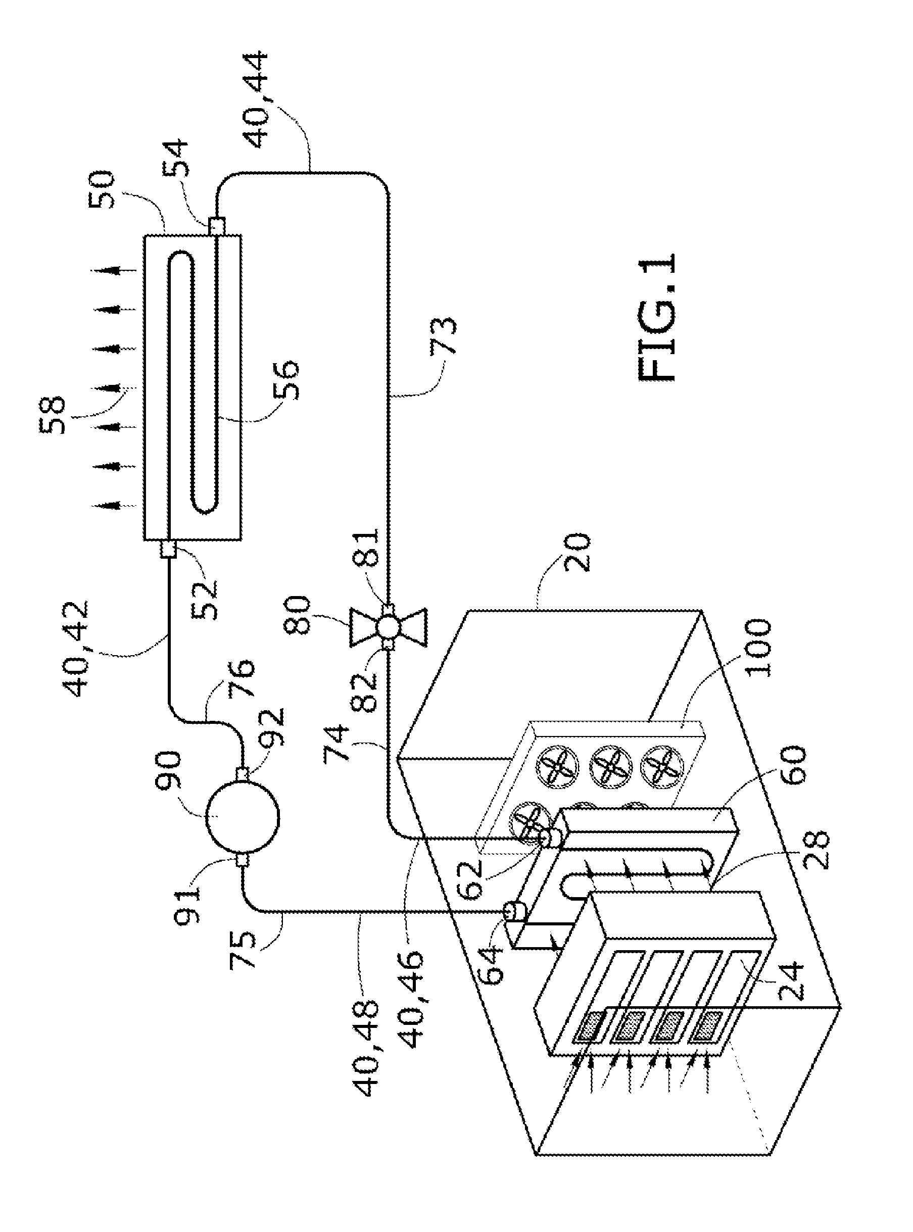
Server cooling system comprising: a condenser 50, an evaporator 60, an expansion valve 80 and a compressor 90, wherein, the outlet 64 of the evaporator 60 is connected to the inlet 91 of the compressor 90 by means of a tube or conduit 75. The outlet 92 of the compressor 90 is connected to the inlet 52 of the compressor 50 by means of a conduit 76. In addition, the outlet 54 of the condenser 50 is connected to the inlet 81 of the electronic expansion valve 80 by means of the tube or conduit 73. While the outlet 82 of the electronic expansion valve 80 is connected to the inlet 62 of the evaporator 60 by means of the tube 74. A server cooling system is achieved with an energy requirement much lower than other systems and is safer, as it avoids the presence of water and furthermore, by using a high evaporation temperature ≧14° C.

Description

OBJECT OF THE INVENTION[0001]The object of the present invention, as indicated in the title of the invention, relates to a cooling system for servers, as well as the method for cooling, wherein the system comprises an evaporator, a condenser, an expansion valve and a compressor, wherein the evaporator has thermal communication with the server in a way that absorbs the heat generated by the server.[0002]An inlet end of the condenser is connected to the outlet end of a compressor by means of tubes. In turn, the inlet end of the compressor is connected to the outlet end of the evaporator. The inlet end of the evaporator is connected to the outlet end of an electronic expansion valve. The inlet end of the electronic expansion valve is connected by means of tubes to the outlet of the condenser.[0003]The system uses a refrigerant fluid for the use of compressors in the fluid line. The refrigerant fluid absorbs the heat generated by the server in the evaporator, changing phase from liquid ...

Claims


Application Information

Patent Timeline
IPC IPC(8): H05K7/20
CPCH05K7/20827G06F1/20G06F2200/201
Inventor ROMANOS TABUENCA, DAVID
Owner PSH ENERGIA
Learn More