
Operation member and electronic devices having the same

a technology of operation member and electronic device, which is applied in the direction of mechanical control device, coupling device connection, electrical apparatus casing/cabinet/drawer, etc., can solve the problems of reducing the product life of electronic components on the circuit board, increasing the cost, and reducing the product life of electronic devices. , to achieve the effect of reducing the product life of electronic components

Active Publication Date: 2015-11-19
LITE ON ELECTRONICS (GUANGZHOU) LTD +1
View PDF9 Cites 26 Cited by
  • Summary
  • Abstract
  • Description
  • Claims
  • Application Information

AI Technical Summary

Benefits of technology

The present invention provides an operation member and an electronic device with the operation member that prevents small particles from entering the device through the gap between the operation member and the casing. This prevents damage to circuit boards and electrical components due to small particles and extends the life of the electronic device. The skirt member of the operation member gathers and prevents small particles from entering the device.

Problems solved by technology

However, when electronic devices are used in relatively poor operating environments, small particles such as powder, wood chips, dust, or any suspended particles can easily enter through the gap and gather on circuit boards inside the electronic device, which may cause damages due to short circuiting or reduce product life of electronic components on the circuit boards.
Thus, the product life of the electronic device is substantially reduced which indirectly leads to cost up.

Method used


Image

  • Operation member and electronic devices having the same
  • Operation member and electronic devices having the same
  • Operation member and electronic devices having the same

Examples


Embodiment Construction

[0018]The aforementioned illustrations and detailed descriptions are exemplarities for the purpose of further explaining the scope of the instant disclosure. Other objectives and advantages related to the instant disclosure will be illustrated in the subsequent descriptions and appended drawings.

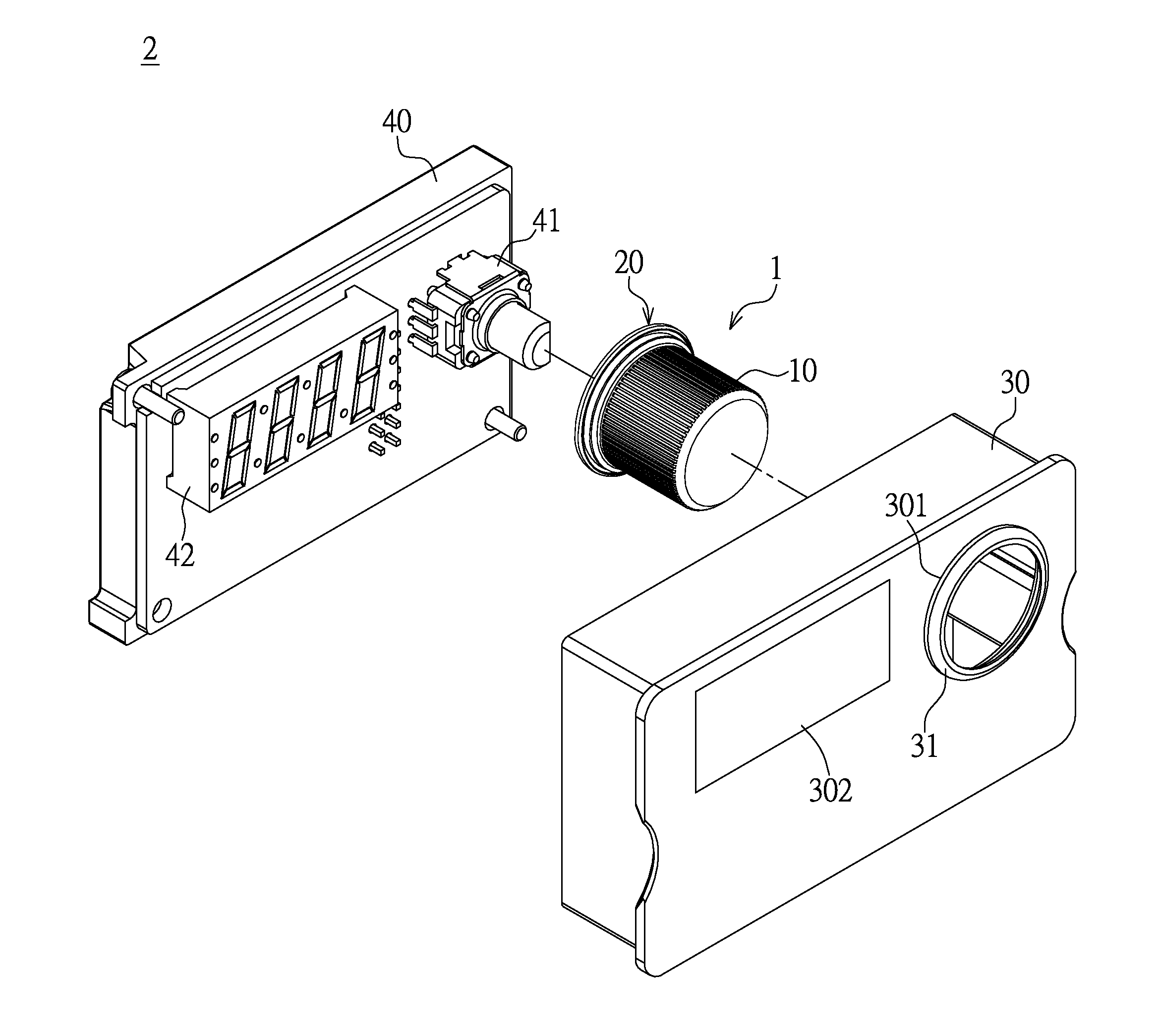
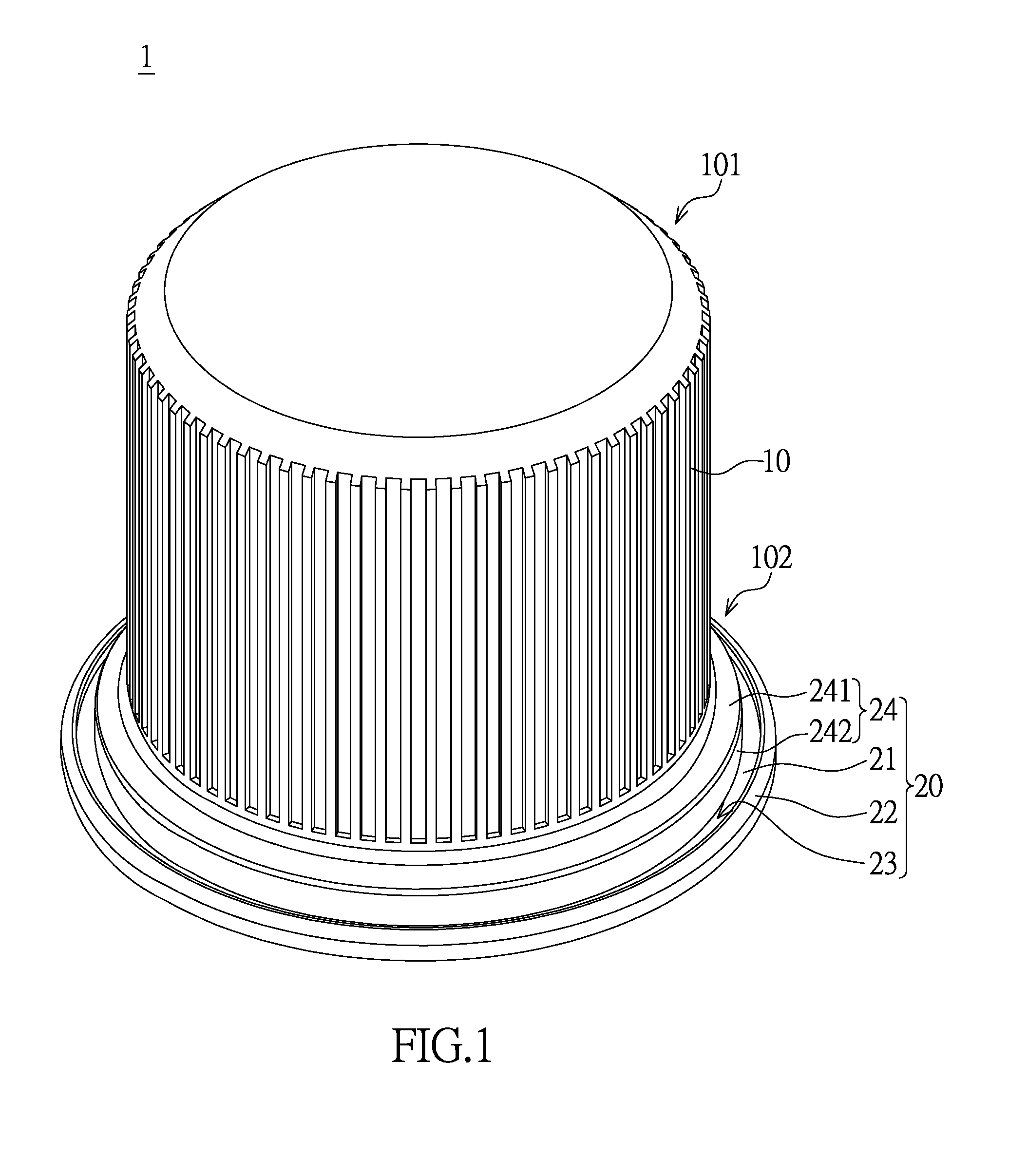
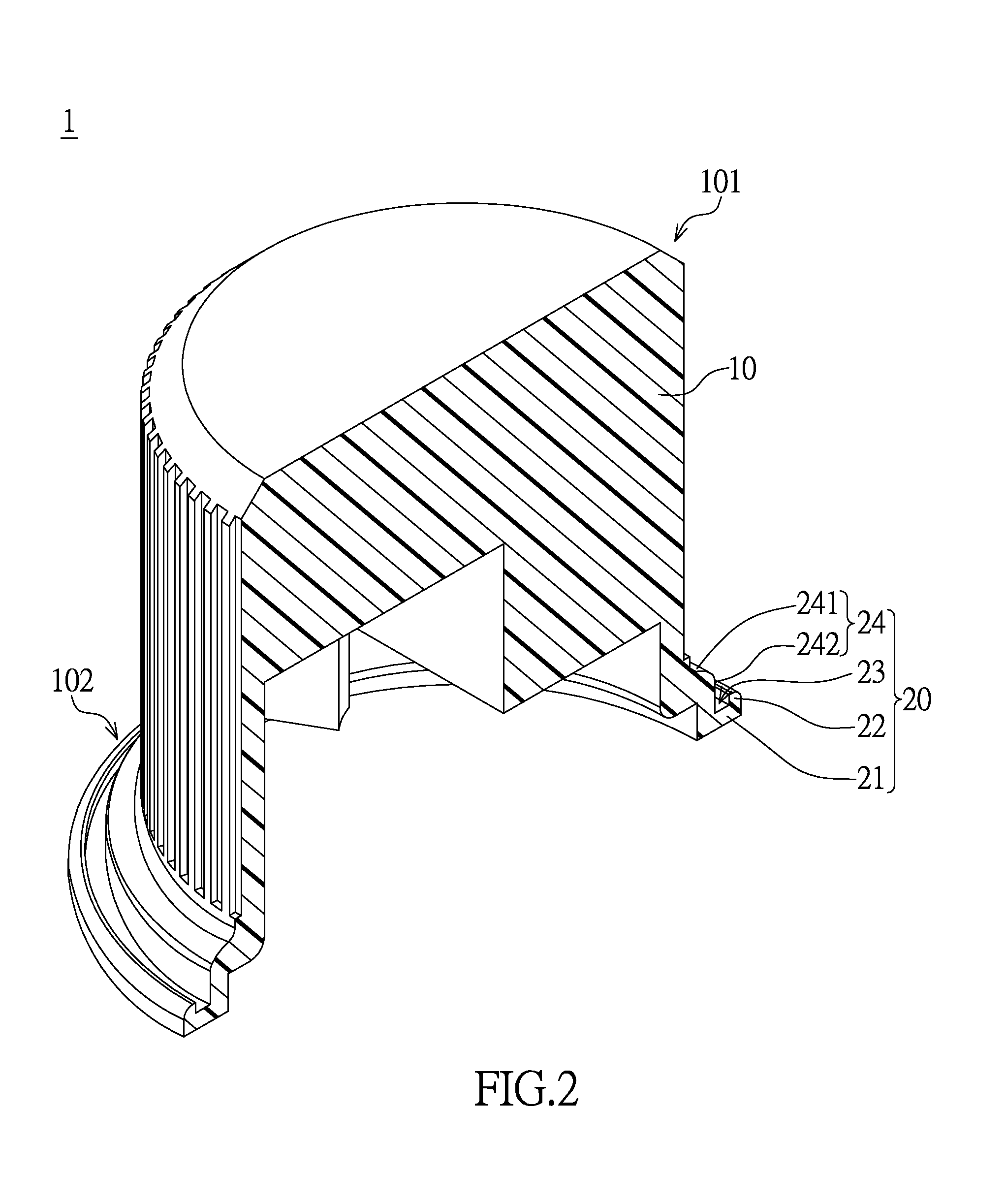
[0019]FIGS. 1 and 2 illustrate schematic diagrams of an operation member in accordance with the instant disclosure. The operation member 1 includes a body 10 and a skirt member 20. The body 10 includes an operating end 101 and a coupling end 102. The operating end 101 provides grip for users. The skirt member 20 is a structure that is arranged at the coupling end 102. The skirt member 20 includes a base plate 21, a wall 22, and a groove 23. The operation member may be a push button, a knob etc. In this embodiment, the operation member as illustrated is a rotary knob for a purpose which will hereafter be made clear.

[0020]Referring to FIGS. 1 and 2, the knob 1 includes a body 10 and a skirt me...


PUM


Abstract

An operation member includes a body having an operating end and a coupling end, and a skirt member. The skirt member is arranged at the coupling end. The skirt member includes a base plate outwardly extending from the coupling end, a wall extending from the base plate, and a groove defined between the outer surface of the wall and the body. The electronic device includes a casing, an operation member, and a circuit module. The casing has portions defining an opening. The circuit module has a circuit board including a controller disposed thereon. The above-mentioned operation member is sleeved onto the controller and passes through the opening. The outer surface of the operation member and the opening define a gap therebetween. The groove is correspondingly arranged proximate to the gap to gather small particles entering the gap.

Description

BACKGROUND OF THE INVENTION[0001]1. Field of the Invention[0002]The instant disclosure relates to an operation member and electronic devices having the same; in particular, to an operation member having a skirt member and an electronic device having the same.[0003]2. Description of Related Art[0004]Typically, knobs on electronic devices are commonly assembled with a knob sleeved onto a variable resistor. In order to provide smooth rotation, the knob and casing of the electronic device are assembled with a predetermined gap therebetween to avoid physical interference. However, when electronic devices are used in relatively poor operating environments, small particles such as powder, wood chips, dust, or any suspended particles can easily enter through the gap and gather on circuit boards inside the electronic device, which may cause damages due to short circuiting or reduce product life of electronic components on the circuit boards. Thus, the product life of the electronic device is...

Claims


Application Information

Patent Timeline
Patent Type & Authority Applications(United States)
IPC IPC(8): G05G1/10H05K5/00H05K5/02
CPCH05K5/0239Y10T74/2084G05G1/10H05K5/0017G05G1/08G05G25/04H05K5/03H01C1/06H01R12/714H01R13/447
Inventor HO, CHUN-LUNGLEE, YI-HSUNOU, MING-WEILIN, YUAN-FU
Owner LITE ON ELECTRONICS (GUANGZHOU) LTD
Learn More