
Low-power miniature led-based UV absorption detector with low detection limits for capillary liquid chromatography

a technology of capillary liquid chromatography and detector limits, which is applied in the direction of photometry using electric radiation detectors, optical radiation measurement, instruments, etc., can solve the problems of unstable light output, long warm-up time, short lifespan, etc., and achieve low detection limits and power requirements. reduced

Active Publication Date: 2015-11-19
BRIGHAM YOUNG UNIV
View PDF9 Cites 13 Cited by
  • Summary
  • Abstract
  • Description
  • Claims
  • Application Information

AI Technical Summary

Benefits of technology

The present invention is a system and method for detecting and quantifying compounds in a liquid using UV LED-based absorption detection. The system eliminates the need for a beam splitter and a reference cell, making it simpler and more portable. The power requirements are reduced, resulting in a smaller and lighter system with low detection limits.

Problems solved by technology

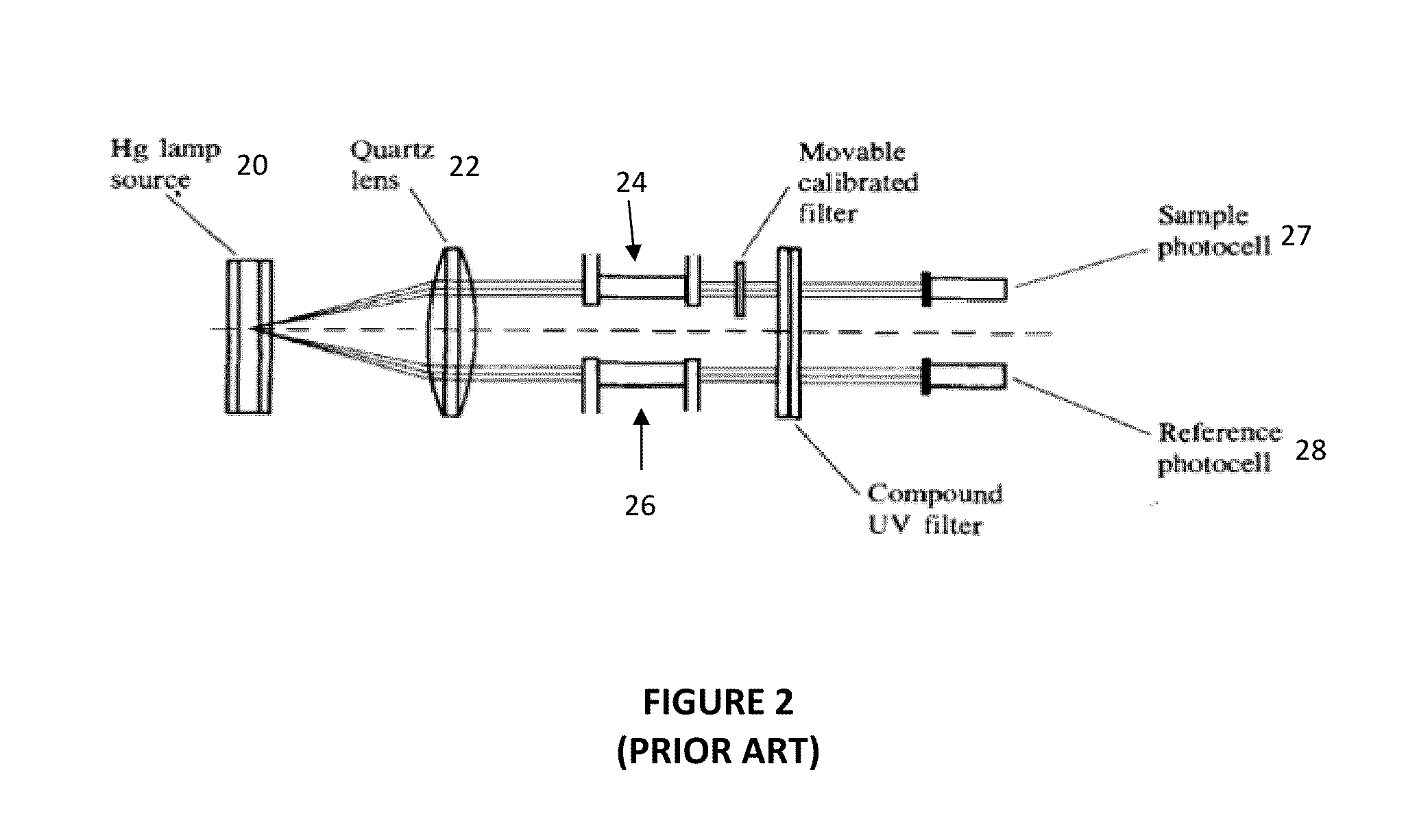
Standard UV light sources, such as a mercury (Hg) lamp 20, suffer from short lifespan, long warm-up time, and unstable light output. FIG. 2 shows that the light source may have to be split using a lens 22, resulting in a reduced light output of the source 20.
Additionally, they are small in size and more compact compared to standard light sources.
However, the detector 32 suffered from high noise, high detection limits and limited linearity.
The system may have also suffered from high stray light levels.
One problem with the LC detection system may be that silicon photodiodes 32 may be more sensitive at higher wavelengths than the UV, which may be evident from a photodiode sensitivity plot.
Therefore, any light emission from an LED 30 at wavelengths higher than the UV may lead to significant stray light in the system.
This system may have suffered from a high level of stray light, which compromised the linear range and detection limits of the system.
However, commercial flow-cell based detectors may have introduced considerable dead volume for capillary columns.
Furthermore, low-volume flow cells (few nLs) may be expensive and suffer from clogging problems due to salt deposition.
However, the use of a slit in front of the capillary column also reduces the light throughput as shown in FIG. 3.

Method used


Image

  • Low-power miniature led-based UV absorption detector with low detection limits for capillary liquid chromatography
  • Low-power miniature led-based UV absorption detector with low detection limits for capillary liquid chromatography
  • Low-power miniature led-based UV absorption detector with low detection limits for capillary liquid chromatography

Examples


Embodiment Construction

[0021]Reference will now be made to the drawings in which the various embodiments of the present invention will be given numerical designations and in which the embodiments will be discussed so as to enable one skilled in the art to make and use the invention. It is to be understood that the following description illustrates embodiments of the present invention, and should not be viewed as narrowing the claims which follow.

[0022]Before beginning, it should be understood that on-column detection may refer to when packed bed material terminates before the end of the column so that the last part of the column is actually empty. But there may also be situations in which the column has packed bed material all the way to the end of the column and a capillary has to be added in order to perform detection in the capillary portion. Accordingly, the embodiments of the invention should all be considered to include both configurations to be within the scope of all embodiments, where detection i...


PUM

PropertyMeasurementUnit
outer diameteraaaaaaaaaa
wavelengthaaaaaaaaaa

Abstract

A system and method for performing UV LED-based absorption detection for capillary liquid chromatography for detecting and quantifying compounds in a liquid, wherein a simplified system eliminates the need for a beam splitter and a reference cell by using a stable UV source, and power requirements are reduced, resulting in a portable and substantially smaller system with relatively low detection limits.

Description

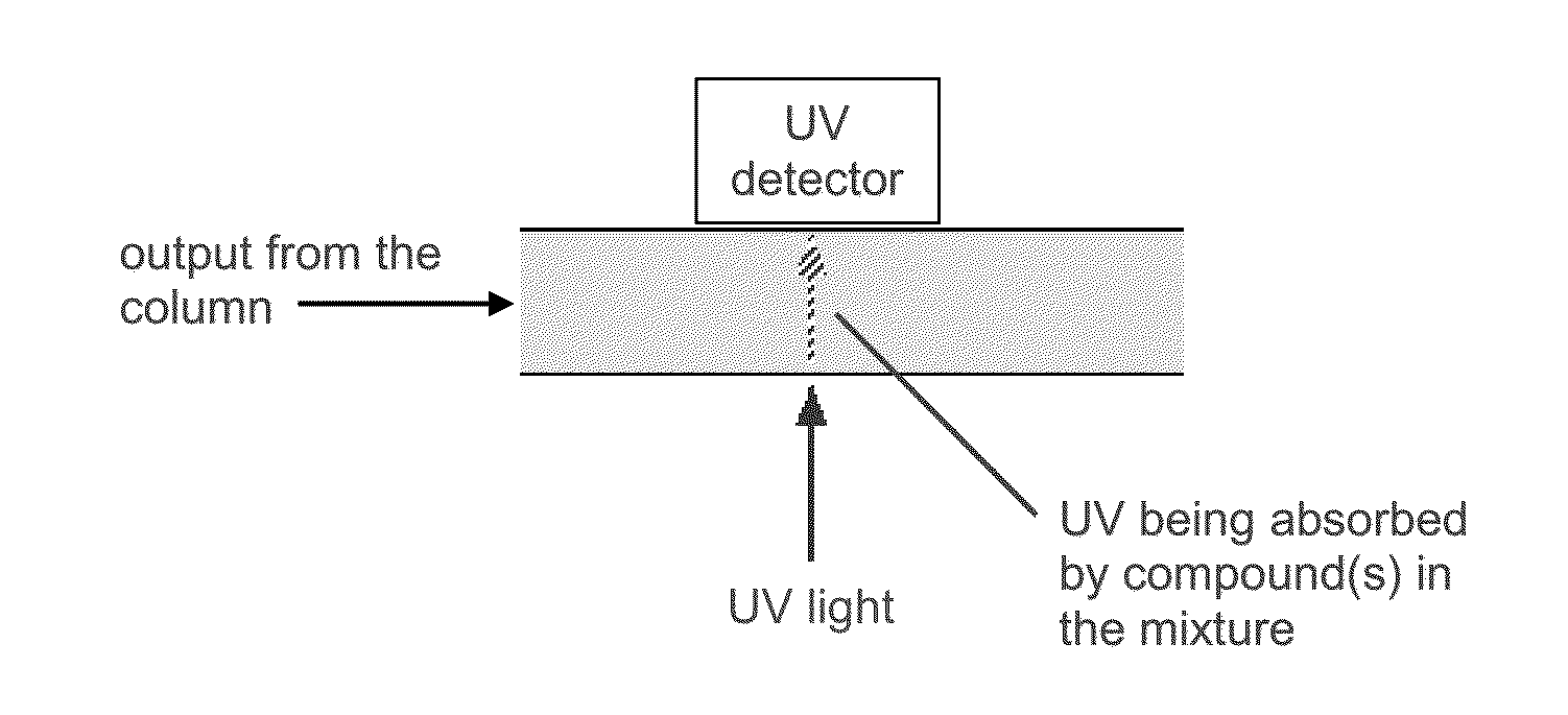
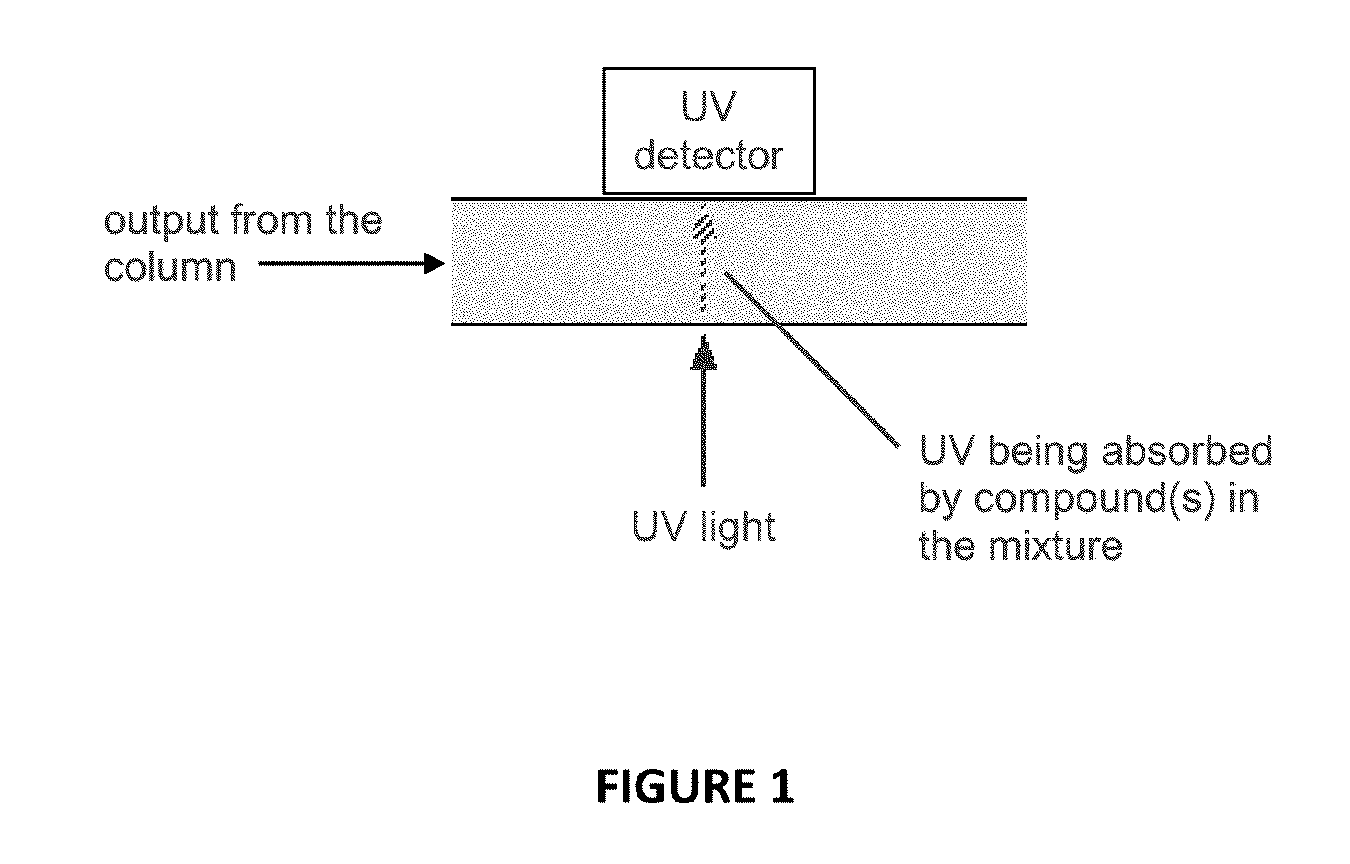
BACKGROUNDDescription of Related Art[0001]Liquid chromatography (LC) is performed in order to analyze the contents of chemicals in a liquid solution. FIG. 1 shows that ultra-violet (UV) light 10 from a light source may be transmitted through a liquid 12 disposed within a capillary column 14 to a UV detector 16. The UV light may be absorbed by compounds in the liquid 12, leaving an intensity of light on the detector 16 that can be interpreted to detect and quantify compounds.[0002]An example of a prior art system used for liquid chromatography (LC) is shown in FIG. 2. Standard UV light sources, such as a mercury (Hg) lamp 20, suffer from short lifespan, long warm-up time, and unstable light output. FIG. 2 shows that the light source may have to be split using a lens 22, resulting in a reduced light output of the source 20. The light source 20 may be split in order to go through a sample material 24 and a reference material 26 and the remaining light is then detected by a sample photo...

Claims


Application Information

Patent Timeline
Patent Type & Authority Applications(United States)
IPC IPC(8): G01N30/74G01N21/05
CPCG01N30/74G01N21/05G01N2201/0693G01N2201/0621G01N2021/0346G01N21/33G01N2201/0221
Inventor FARNSWORTH, PAUL B.SHARMA, SONIKATOLLEY, H. DENNISLEE, MILTON L.
Owner BRIGHAM YOUNG UNIV
Learn More