In-line plasma CVD apparatus

a plasma cvd and apparatus technology, applied in the direction of chemical vapor deposition coating, coating, electric discharge tube, etc., can solve the problems of thick deposits attached, deformation of coatings, and other problems, and achieve the effect of stably performing the operation without cleaning for a long time and high production efficiency

Inactive Publication Date: 2015-11-19
KOBE STEEL LTD
View PDF5 Cites 12 Cited by
  • Summary
  • Abstract
  • Description
  • Claims
  • Application Information

AI Technical Summary

Benefits of technology

[0012]Accordingly, it is an object of the present invention to provide an in-line plasma CVD apparatus with a high production efficiency that is less likely to deposit a CVD coating on a part other than a substrate, thereby being capable of stably performing its operation without cleaning for a long time.

Problems solved by technology

The coating deposited thick in this way tends to be peeled off and fly apart, which can result in a defective coating.
Further, when the coating deposited by the plasma CVD method is an insulating coating, such as a DLC, other problems can also be caused.
Thus, even if the same power conditions are set, the state of generation of the plasma disadvantageously fluctuates, and thus the properties of the coating are also varied.
As a result, there arises a problem that the deposits attached thickly might fly apart.
Thus, the generation of the plasma that would occur with an inner wall of the chamber serving as one electrode becomes unstable, or process requirements can deviate from the optimal ones.

Method used


Image

  • In-line plasma CVD apparatus
  • In-line plasma CVD apparatus
  • In-line plasma CVD apparatus

Examples


first embodiment

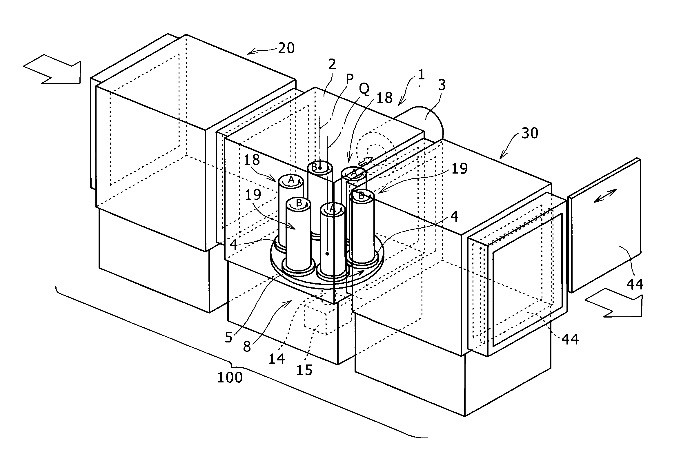
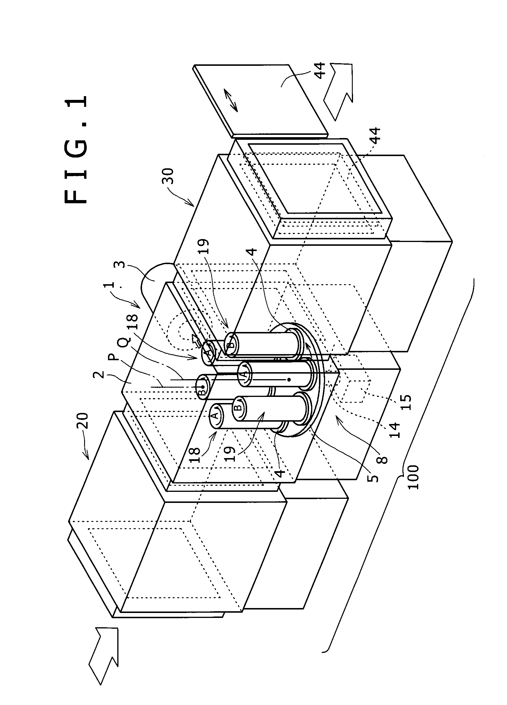
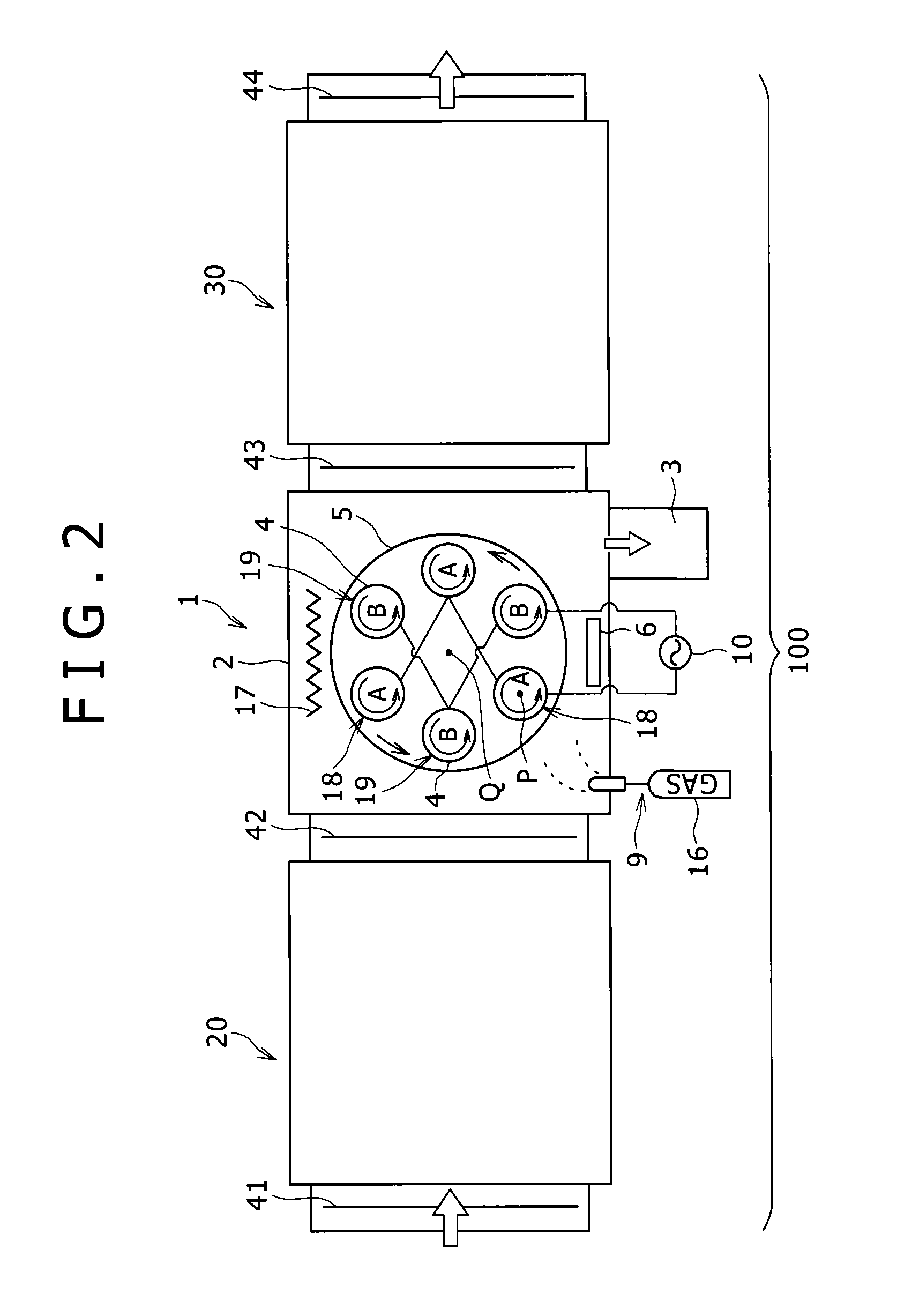
[0035]FIG. 1 is a perspective view showing an entire structure of a plasma CVD apparatus 100 according to a first embodiment of the invention, and FIG. 2 is a top view thereof.

[0036]The plasma CVD apparatus 100 includes a deposition chamber 1 with a plasma CVD mechanism, a load-lock chamber 20 which is another compartment disposed on an upstream side of the deposition chamber 1, and a load-lock chamber (compartment) 30 which is a further compartment disposed on a downstream side of the deposition chamber 1. The terms “upstream” and “downstream” as used herein are based on the transport direction of the substrate W. At an inlet of the load-lock chamber 20, an isolation valve 41 is placed. An isolation valve 42 is placed between an outlet of the load-lock chamber 20 and an inlet of the deposition chamber 1. An isolation valve 43 is placed between an outlet of the deposition chamber 1 and an inlet of the load-lock chamber 30. An isolation valve 44 is placed at an outlet of the load-loc...

second embodiment

[0095]Now, a plasma CVD apparatus 200 according to a second embodiment of the invention will be described with reference to FIGS. 5A to 5D. The plasma CVD apparatus 200 of the second embodiment differs from the above-mentioned plasma CVD apparatus 100 of the first embodiment in arrangement of the substrates W on the substrate table. Except for the above-mentioned point, the plasma CVD apparatus 200 of the second embodiment is the substantially same as that of the first embodiment, and thus the same parts as the above-mentioned description will not be repeated below.

[0096]FIG. 5A illustrates the plasma CVD apparatus 200 in the second embodiment. FIG. 5A corresponds to FIG. 4A.

[0097]As shown in FIG. 5A, the plasma CVD apparatus 200 includes a deposition chamber 201 provided with a plasma CVD mechanism and having a vacuum chamber 202, a load-lock chamber 220 disposed on the upstream side of the deposition chamber, and a load-lock chamber 230 disposed on the downstream side of the depos...

third embodiment

[0100]Now, a plasma CVD apparatus 300 according to a third embodiment of the invention will be described with reference to FIG. 6A. The plasma CVD apparatus 300 differs from the plasma CVD apparatus 100 of the above-mentioned first embodiment in arrangement of the substrates W. Except for the above-mentioned point, the plasma CVD apparatus 300 of the third embodiment is the substantially same as that of the first embodiment, and thus the same parts as the above-mentioned description will not be repeated below.

[0101]FIG. 6A illustrates the plasma CVD apparatus 300 in the third embodiment. FIG. 6A is a plan view explaining the operation states of the in-line plasma CVD apparatus, and corresponding to FIG. 4A.

[0102]As shown in FIG. 6A, the plasma CVD apparatus 300 includes a deposition chamber 301 provided with a plasma CVD mechanism and having a vacuum chamber 302, a load-lock chamber 320 disposed on the upstream side of the deposition chamber, and a load-lock chamber 330 disposed on ...


PUM

PropertyMeasurementUnit
frequencyaaaaaaaaaa
frequencyaaaaaaaaaa
frequencyaaaaaaaaaa

Abstract

Provided is an in-line plasma CVD apparatus (100) capable of performing a deposition process at a high production efficiency while maintaining stable deposition conditions, without spending time and energy on cleaning and the like even when in use for a long time. This plasma CVD apparatus (100) is equipped with a deposition chamber (1) and load-lock chambers (20, 30) which are separate from the deposition chamber (1). The apparatus (100) is of the in-line-type for conveying a substrate between these chambers and producing a film on the substrate. The deposition chamber (1) is equipped with a vacuum chamber (2), a vacuum exhaust means (3) for discharging the air inside the vacuum chamber (2), a gas supply unit (9) for supplying a source gas into the vacuum chamber (2), and a plasma generation power supply (10) for generating plasma inside the vacuum chamber (2). Substrates in the deposition chamber (1) are divided into a first group (18) connected to one pole of the plasma generation power supply (10), and a second group (19) connected to the other pole of the plasma generation power supply (10). The plasma is produced between the first group (18) and the second group (19) which have different polarities from one another.

Description

TECHNICAL FIELD[0001]The present invention relates to a plasma CVD apparatus for forming a CVD coating on a substrate, and more particularly, to an in-line plasma CVD apparatus with a high production efficiency while maintaining stable deposition conditions.BACKGROUND ART[0002]Engine parts, etc., of automotives, such as a piston ring, are required to have good wear resistance, heat resistance, seizure resistance, and the like. For this reason, these mechanical parts are subjected to a wear-resistant coating, such as a diamond-like-carbon (DLC), by using a plasma CVD method.[0003]When forming the coating on the above-mentioned substrate by the plasma CVD method, numerous substrates are preferably accommodated in a vacuum chamber and coated at one time in terms of productivity. In order to process the numerous substrates at one time in this way, the coatings formed on the respective substrates have to have uniform thickness and film properties among the substrates. Thus, in a conventi...

Claims


Application Information

Patent Timeline
Patent Type & Authority Applications(United States)
IPC IPC(8): C23C16/54C23C16/44C23C16/458C23C16/503
CPCC23C16/54C23C16/4584C23C16/4412C23C16/503C23C16/4409C23C16/505C23C16/26C23C16/4401C23C16/4588H01J37/32568H01J37/32706H01J37/32779H01J37/32899H01J37/32715H01J37/32853H01L21/67173H01L21/67201H01L21/67754H01L21/6776
Inventor TAMAGAKI, HIROSHIHAGA, JUNJI
Owner KOBE STEEL LTD
Why Eureka
Try Eureka