Hydrostatic transmission with spool valve driven motor

Active Publication Date: 2015-11-12
PARKER HANNIFIN MFG SWEDEN
View PDF2 Cites 4 Cited by
  • Summary
  • Abstract
  • Description
  • Claims
  • Application Information

AI Technical Summary

Benefits of technology

The present invention is an improved hydrostatic transmission that solves issues with conventional configurations. It includes a center section with an enhanced spool valve that connects to a pump and motor in both supply and return flow directions, resulting in a more compact configuration. This prevented wear and tear on the wheel hub from large side loads. The transmission is enclosed by a housing with only the center section reacting hydraulic separating forces. The top housing has sufficient volume to allow fluid to expand as temperature increases, eliminating the need for an external tank. The hydrostatic transmission can be used in light vehicles, such as turf machines and lawn mowers, for full wheel torque driving.

Problems solved by technology

Spool valve driven motors are known in the art for use in various applications, but conventional configurations have proven to be deficient for wheel drives, and hence have not been practical for transmission applications.
Because the spool valve bore normally serves as the inboard bearing, large side loads may be transferred to the spool valve resulting in significant wearing of the spool valve bore.
To accommodate such loads and otherwise provide suitable performance, it remains difficult to provide a compact spool valve motor configuration that is suitable for hydrostatic transmissions applied to light vehicle wheel drives.
Accordingly, because of the size constraints associated with light vehicles, it has been difficult to provide a hydrostatic transmission for a full wheel torque configuration that is compact, cost effective, and easy to assemble.

Method used


Image

  • Hydrostatic transmission with spool valve driven motor
  • Hydrostatic transmission with spool valve driven motor
  • Hydrostatic transmission with spool valve driven motor

Examples


Embodiment Construction

[0024]Embodiments of the present invention will now be described with reference to the drawings, wherein like reference numerals are used to refer to like elements throughout. It will be understood that the figures are not necessarily to scale.

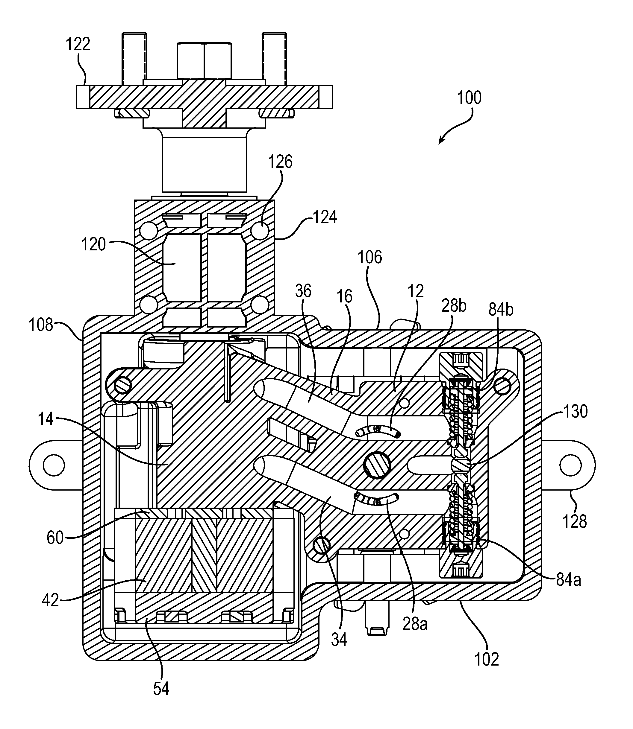
[0025]As referenced above, the present invention pertains to vehicle configurations in which a hydrostatic transmission provides for full wheel torque by connecting the hydrostatic transmission output directly to a wheel hub without any intervening gear reduction element. Specifically, a pump is driven by the prime mover (engine). The motor typically is of larger displacement (e.g., 20:1) as compared to the pump, which provides speed reduction and torque amplification of the prime mover to drive the wheel. It will be appreciated by those skilled in art that the hydrostatic transmission and the various components described herein may be reoriented as needed to accommodate different wheels, such as left versus right side wheels, and back versus ...


PUM


Abstract

A center section / motor sub-assembly for use in a hydrostatic transmission includes a center section having a pump running face for interfacing with a pump and a motor running face for interfacing with a motor, and a bore extending laterally through the center section from the motor running face. A spool valve is received in the bore and includes a fluid pathway for providing fluid communication between the pump running face and the motor running face. The sub-assembly further includes a motor having a rotor and a motor stator secured to the center section adjacent to the motor running face in a manner that permits rotation of the rotor. The center section is configured for the hydraulic separating forces of the motor to be reacted only into the center section. A hydrostatic transmission includes the sub-assembly enclosed by a housing, in combination with a pump and output shaft.

Description

RELATED APPLICATION DATA[0001]This application claims priority to U.S. Provisional Patent Application Ser. No. 61 / 989,808, filed on May 7, 2014, the content of which is incorporated here by reference.FIELD OF INVENTION[0002]The present invention relates generally to hydraulic pumps and motors, and more particularly to a hydrostatic transmission having a pump, a rotary spool valve incorporated as part of a motor, and a center section that provides a fluid connection between the pump and motor for the flow of hydraulic fluid.BACKGROUND[0003]A prime mover, such as an internal combustion engine or the like, can be connected to a hydrostatic transmission to drive a wheel in a light vehicle. A hydrostatic transmission is particularly suitable to provide traction drive for light vehicles such as turf machines, lawn tractors, ride-on lawn mowers, and like devices. A simple usage of hydrostatic transmissions is on zero-turn radius vehicles, including zero-turn radius mowers and tractors.[000...

Claims


Application Information

Patent Timeline
IPC IPC(8): F16H39/42F15B13/02F15B7/06F16H61/4035B60K17/356
CPCF16H39/42F16H61/4035F15B13/025F15B7/06B60K17/356B60K17/105B60K17/10B60Y2200/223
Inventor SIMON, MATTHEW HERMANHEATHCOAT, JR., DAVID MARK
Owner PARKER HANNIFIN MFG SWEDEN
Why Eureka
Try Eureka