Portable multi-function cable tester

a multi-functional, cable tester technology, applied in the direction of instruments, line-transmission details, measurement instrument housings, etc., can solve problems such as faulty and potentially dangerous cable tests, and achieve the effects of reducing confusion and time, improving trouble shooting speed, and convenient us

Active Publication Date: 2015-11-05
THE UNITED STATES OF AMERICA AS REPRESENTED BY THE SECRETARY OF THE NAVY
View PDF1 Cites 19 Cited by
  • Summary
  • Abstract
  • Description
  • Claims
  • Application Information

AI Technical Summary

Benefits of technology

[0010]Among other advantages, by using the methods and apparatus described herein, various capabilities for testing cable continuity may be improved, such as ease of use by reducing the confusion and time required when conducting tests on electronic cables, returning fully automated test results to the user through a digital display, requiring little or no technical expertise by the user operating the apparatus, and increased trouble shooting speed. Other advantages will be recognized by those of ordinary skill in the art.

Problems solved by technology

Communication during testing may be impeded by lack of radio connectivity, human error, and miscommunication between technicians resulting in faulty and potentially dangerous cable tests.

Method used


Image

  • Portable multi-function cable tester
  • Portable multi-function cable tester
  • Portable multi-function cable tester

Examples


Embodiment Construction

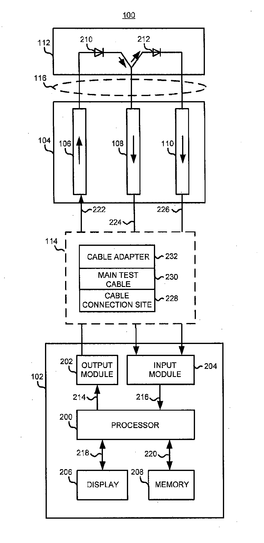
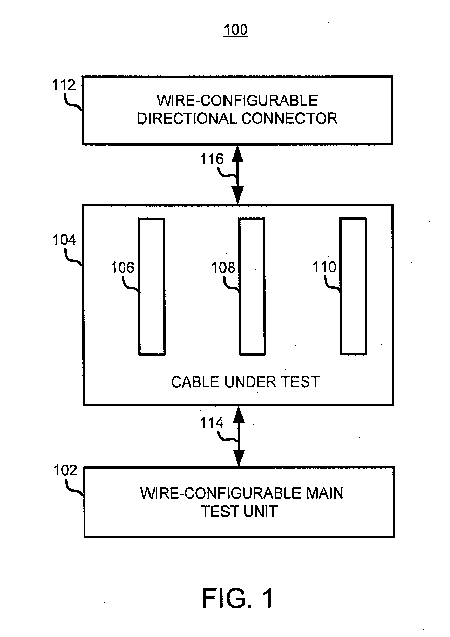
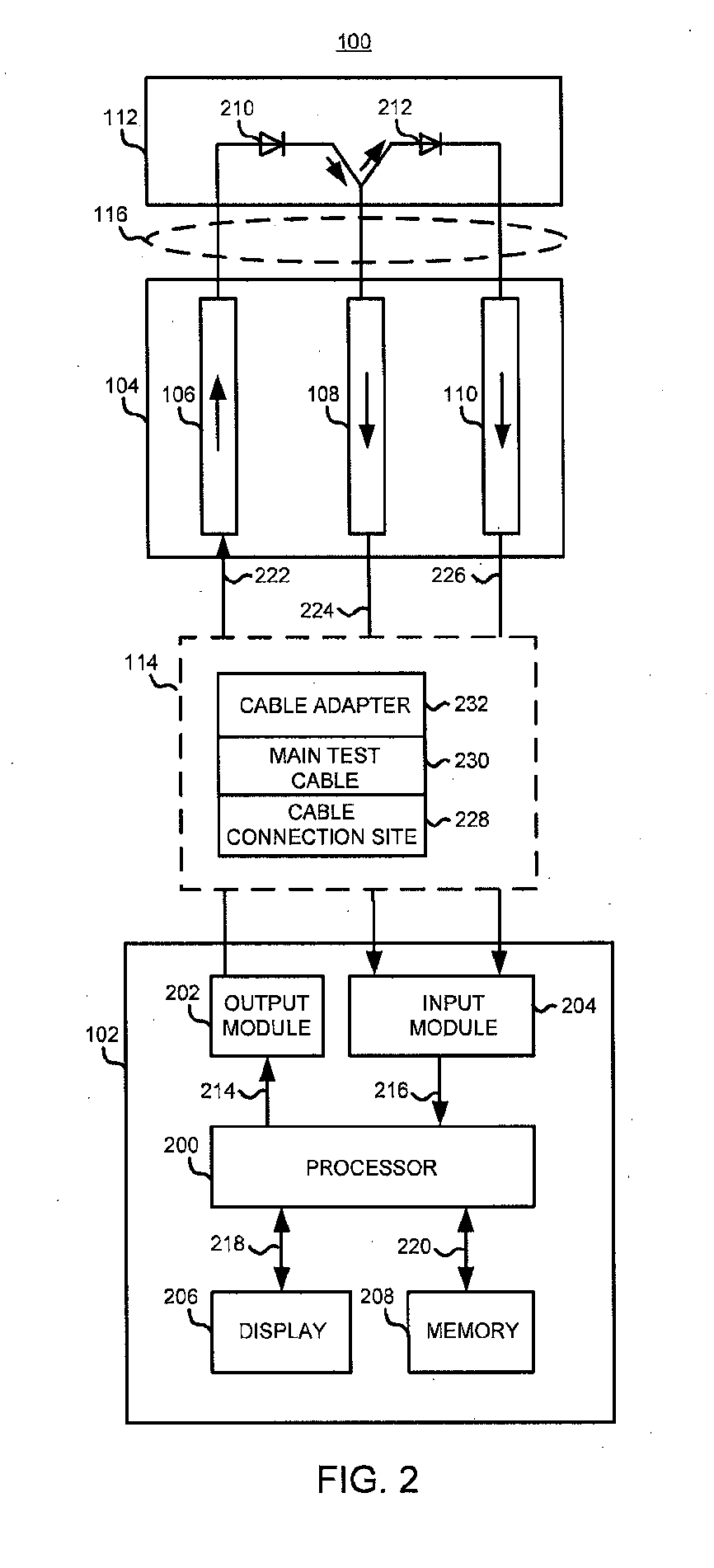
[0027]FIG. 1 shows a block diagram illustrating one example of a system 100 employing an apparatus 102, such as a wire-specific voltage pulse generation main test unit (MTU 102), a cable under test 104, and a wire-configurable directional connector 112. In this example, the cable under test 104 comprises a first wire, a second wire, and a third wire, such as wire 106, wire 108, and wire 110, respectively. Those of ordinary skill in the art will recognize that the cable under test 104 may comprise any number of wires.

[0028]MTU 102 may be supported by a chassis and stored in a protective case, such as a pelican case, that allows for protection from shock and environmental hazards. Further, MTU 102 may be powered by either an external power source directly attached to the MTU 102 or by using a permanent power source, such as a ship power or a wall outlet, by connecting a power cable from the permanent power source to the MTU 102 via a power input connector. The external power source ca...


PUM

PropertyMeasurementUnit
current ratingaaaaaaaaaa
voltageaaaaaaaaaa
returning voltageaaaaaaaaaa

Abstract

The methods and apparatus described herein are designed and configured to allow one user to test cable continuity using a wire-configurable directional connector. The methods and apparatus may transmit a first and second voltage pulse through a first and second wire of a cable under test, respectively, having a wire-configurable directional connector attached. Both voltage pulses travel through the wire-configurable directional connector. The first voltage pulse selectively leaves at least one of the second wire and a third wire of the cable under test and the second voltage pulse selectively leaves the third wire. The methods and apparatus may store a pre-determined pattern of a returning voltage pulse specific to the cable under test, and determine a state of the first, second, and third wires in response to receiving the first and second voltage pulses.

Description

CROSS REFERENCE TO RELATED APPLICATION[0001]This non-provisional patent application claims the benefit of and priority from U.S. provisional patent application No. 61 / 973,319 filed Apr. 1, 2014, the disclosure of which is expressly incorporated herein by reference.STATEMENT REGARDING FEDERALLY SPONSORED RESEARCH OR DEVELOPMENT[0002]The invention described herein may be manufactured, used and licensed by or for the United States Government for any governmental purpose without payment of any royalties thereon. This invention (Navy Case 103,206) is assigned to the United States Government and is available for licensing for commercial purposes. Licensing and technical inquiries may be directed to the Technology Transfer Office, Naval Surface Warfare Center Crane, email: Cran_CTO@navy.mil.FIELD OF THE DISCLOSURE[0003]The disclosure relates generally to testing cable continuity, and more particularly, using a wire-configurable directional connector to test cable continuity.BACKGROUND[0004...

Claims


Application Information

Patent Timeline
Patent Type & Authority Applications(United States)
IPC IPC(8): G01R31/02G01R3/00G01R1/04G01R31/58
CPCG01R31/026G01R1/0416Y10T29/49171G01R3/00G01R31/021G01R1/04G01R31/11G01R31/58G01R31/54G01R31/52
Inventor DAVIS, BRENT E.
Owner THE UNITED STATES OF AMERICA AS REPRESENTED BY THE SECRETARY OF THE NAVY
Why Eureka
Try Eureka