
Trimmed Lock-Up Clutch

Active Publication Date: 2015-10-29
TWIN DISC
View PDF3 Cites 5 Cited by
  • Summary
  • Abstract
  • Description
  • Claims
  • Application Information

AI Technical Summary

Benefits of technology

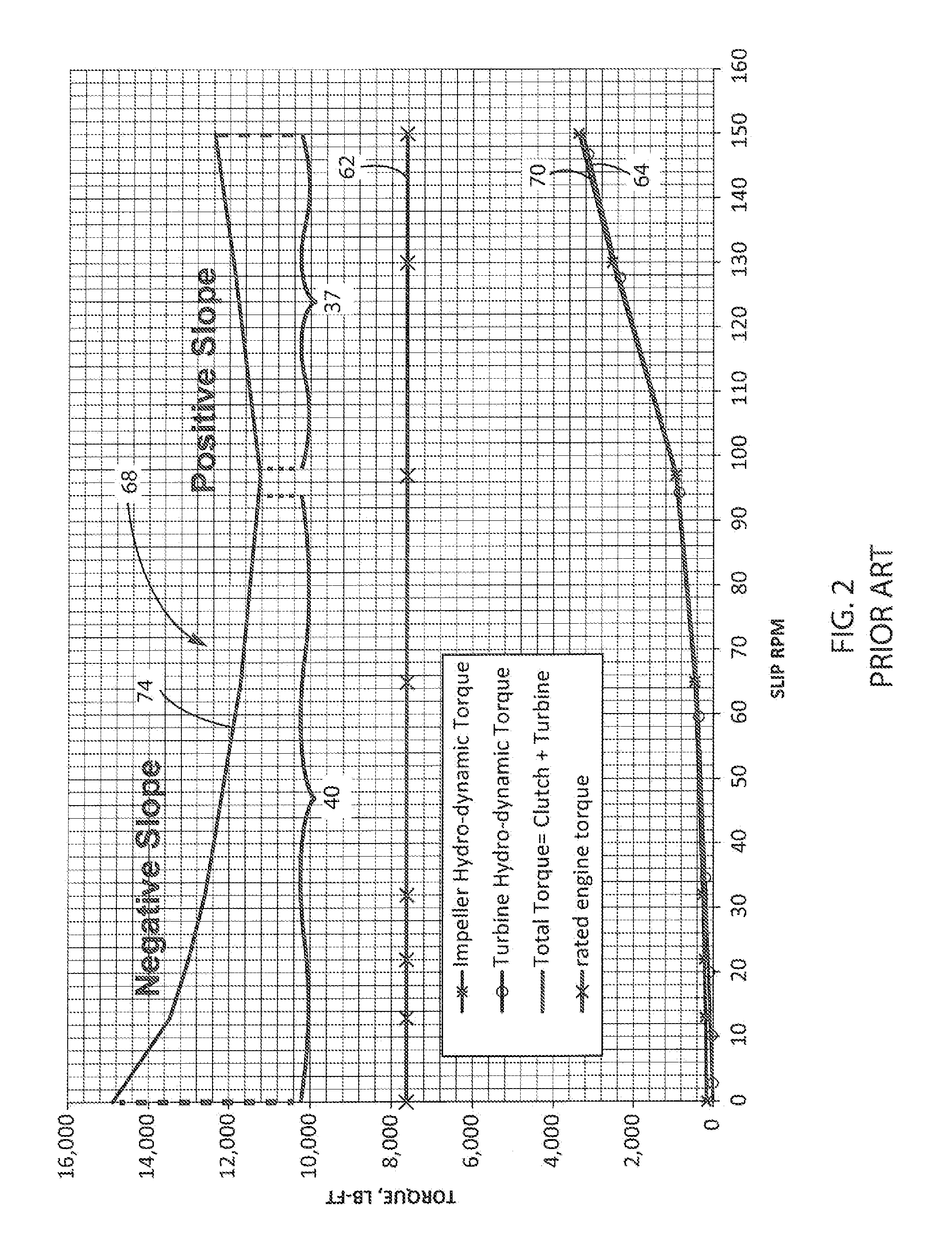
The present invention relates to a clutch slip control system for vehicles that improves stability, component life, and performance. The system uses a pressure and slip speed scheduling technique to reduce vibrations transmitted to the powertrain through the torque converter clutching device. The method involves controlling at least one of clutch engagement pressure, input shaft speed, and output shaft speed, and maintaining a positive slope of clutch coefficient of friction over clutch slip speed. The closed loop control of clutch pressure and clutch slip speed involves fully engaging the clutch for a predetermined time, adjusting clutch engagement pressure to allow for a predetermined clutch slip speed, and monitoring clutch engagement pressure. This results in a negative impact on the vibration of the drive train, improving stability and performance.

Problems solved by technology

An unfortunate aspect of full clutch engagement is that the engine and any subsequent moving parts produce torsional vibrations, normally absorbed by the torque converter, that are passed directly through the clutch to the remainder of the powertrain.
These resonant frequencies produce torsional vibrations when the system is operated under certain loads.
These torsional vibrations produce damaging pulsations therein if not properly dampened that can significantly reduce the life of the power train components.
As a result, it is desirable to dampen these torsional vibrations as they are known to physically vibrate the system with such force that, not only can the clutch be damaged, but the entire drive line may be damaged as well.
Both the engine and the pump produce vibratory pulsations during the power stroke which manifest as torsional vibrations in the system.
While the couplings are effective, they come at a significant cost and add considerable size to the torque converter and clutch mechanism.
This transfer is nonlinear in nature, and the potential for instability is present at various slip speeds.
As a result, there is a tendency for the slippage control to completely engage the clutch with maximum pressure in response to a condition for which the measured slip exceeds the desired slip.
Because the lock-up clutch is fully engaged, the hydraulic torque converter does not have the ability to absorb the torsional vibrations that are created by the engine and the fracking pump.
Torsional vibrations are known to spike in this fully locked condition, especially if a critical harmonic frequency exists in the operating range.
Excessive torsional vibrations can reduce the life of various components in the powertrain system.

Method used


Image

  • Trimmed Lock-Up Clutch
  • Trimmed Lock-Up Clutch
  • Trimmed Lock-Up Clutch

Examples


Embodiment Construction

[0042]The present invention and the various features and advantageous details thereof are explained more fully with reference to the non-limiting embodiments described in detail in the following description.

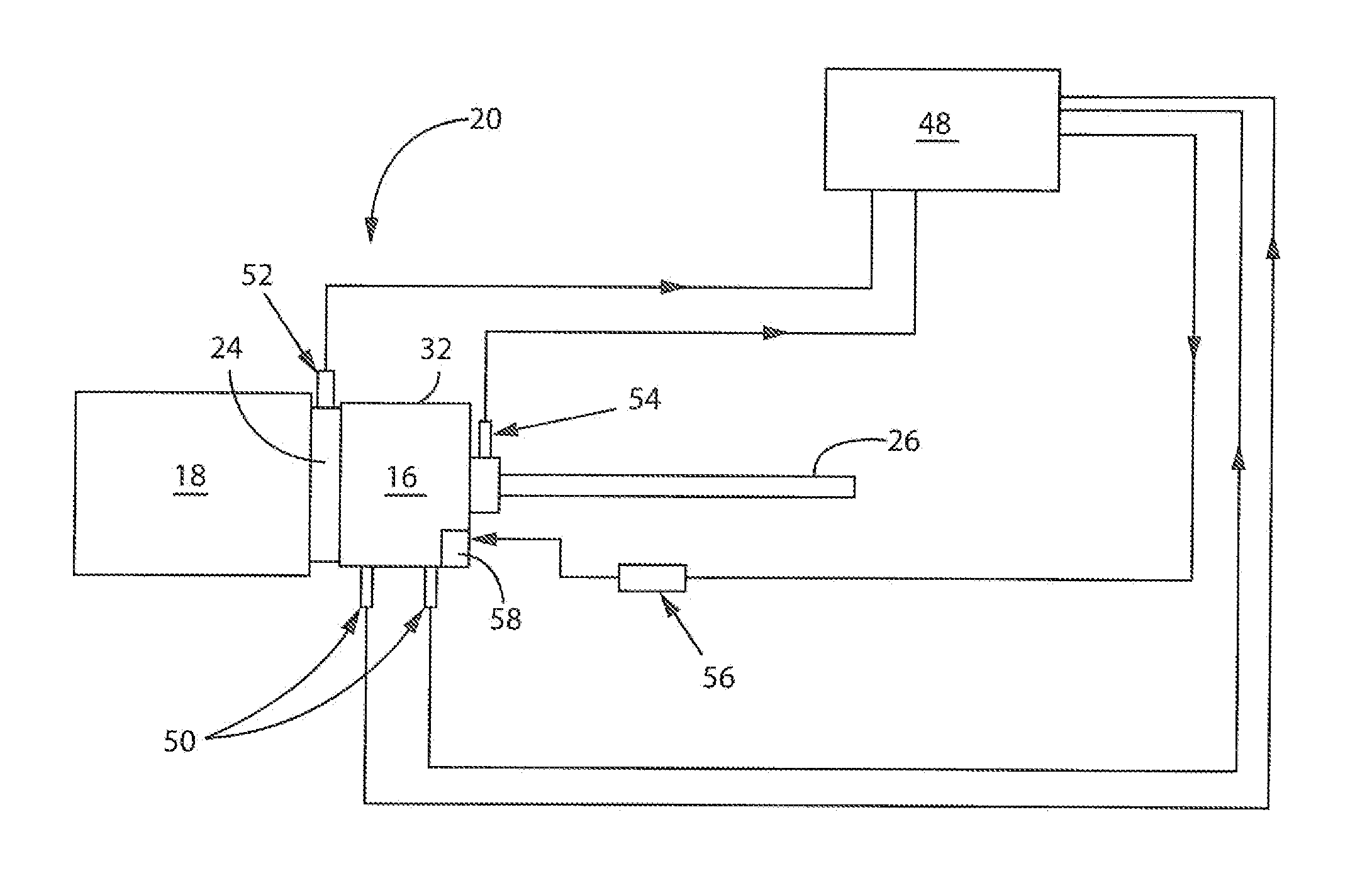
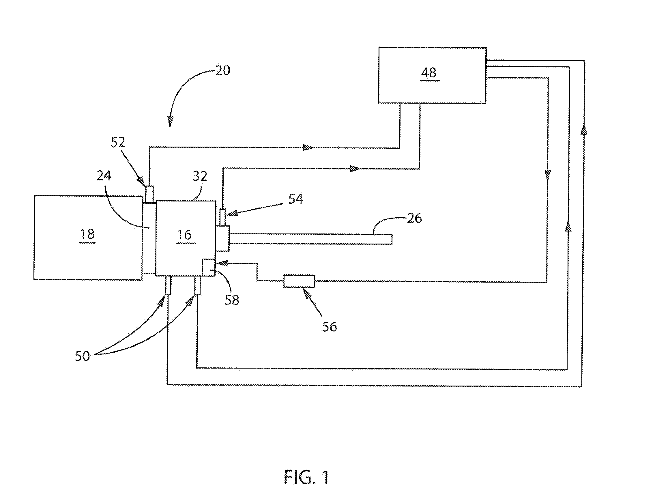
[0043]Beginning with FIG. 1, the lock-up clutch 16 is nested inside a hydraulic torque converter 32. A clutch apply piston 58 is opposed by the torque converter's internal circuit pressure. As a result, total clutch torque capacity is determined by the difference between clutch apply pressure minus the torque converter's “basic” pressure. This is commonly referred to as differential pressure.

[0044]The implementation of this “trimmed lock-up clutch” includes the control of the lock-up clutch pressure by means of a proportional pressure valve 56 that is in turn controlled by an electronic control unit 48. The electronic control 48 may monitor lock-up clutch pressure, converter outlet pressure, torque converter input and output speed, and an engine load signal.

[0045]In order to redu...


PUM


Abstract

In order to reduce torsional vibrations in a drive including a torque converter with a turbine and impeller, clutch slip speed of the drive is adjusted by manipulation of clutch pressure. This may be done in either closed loop mode or open loop mode by setting the clutch pressure to a predetermined value or continuously adjusting clutch pressure. Pressure is adjusted to produce a positively sloped function of sensed total torque of the clutch and turbine over the clutch slip speed. This produces extended service life of the drive train components, greater efficiency of the torque converter, and smoother operation of the drive.

Description

BACKGROUND OF THE INVENTION[0001]1. Field of the Invention[0002]This invention relates to a system for controlling the slip of a clutch transferring rotational force from a power source to an output shaft, and more particularly, to controlling the clutch pressure and clutch slip speed to reduce torsional vibrations generated by the entire powertrain.[0003]2. Background of the Invention[0004]The torque converter clutch is a fluid operated friction device engageable to couple an input shaft to an output shaft via a clutch. Typically the clutch is either fully released to permit unrestrained slippage between the input shaft and the output shaft, or fully engaged, also referred to as “locked-up,” to prevent such slippage entirely. An unfortunate aspect of full clutch engagement is that the engine and any subsequent moving parts produce torsional vibrations, normally absorbed by the torque converter, that are passed directly through the clutch to the remainder of the powertrain. Torsiona...

Claims


Application Information

Patent Timeline
IPC IPC(8): F16D48/06F16D7/02
CPCF16D7/02F16D48/06F16D2500/3024F16D2500/30406F16D2500/3163F16D2500/3166F16D2500/50293F16D2500/70406F16D2500/7061F16D2500/70652F16D2500/70426F16D2500/70444
Inventor SMITH, WILLIAM D.SHAW, RICHARD A.
Owner TWIN DISC
Learn More