
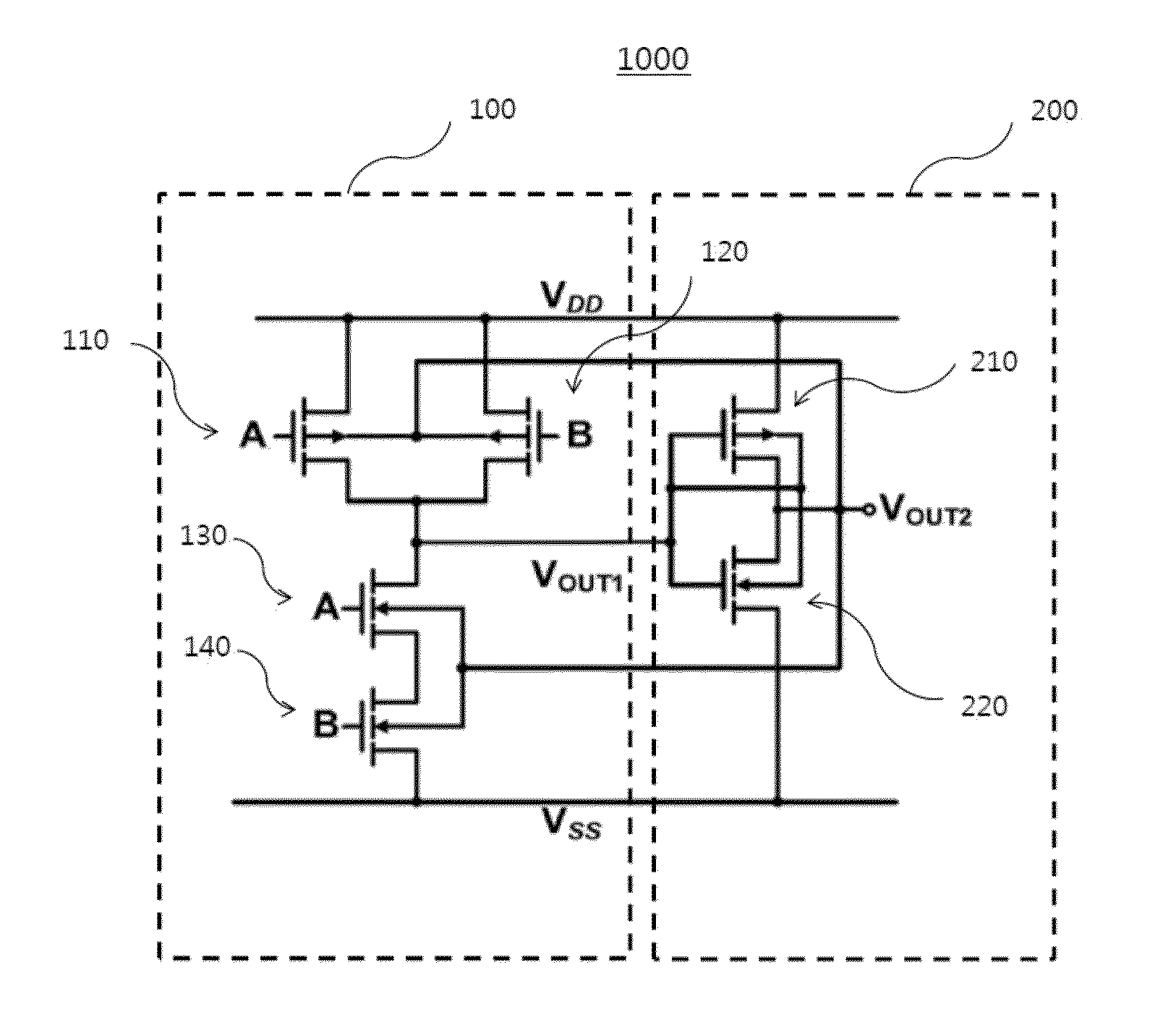
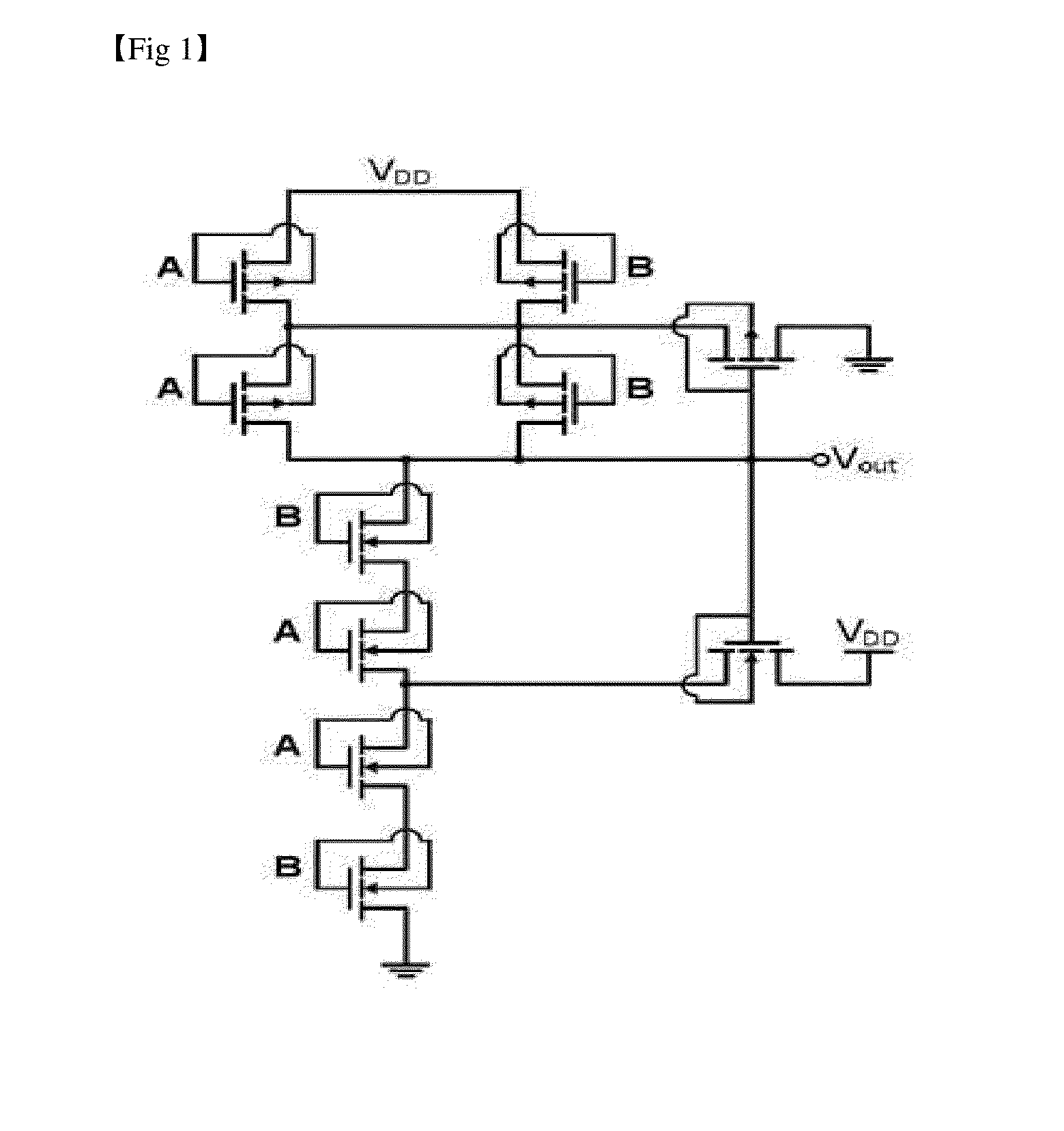
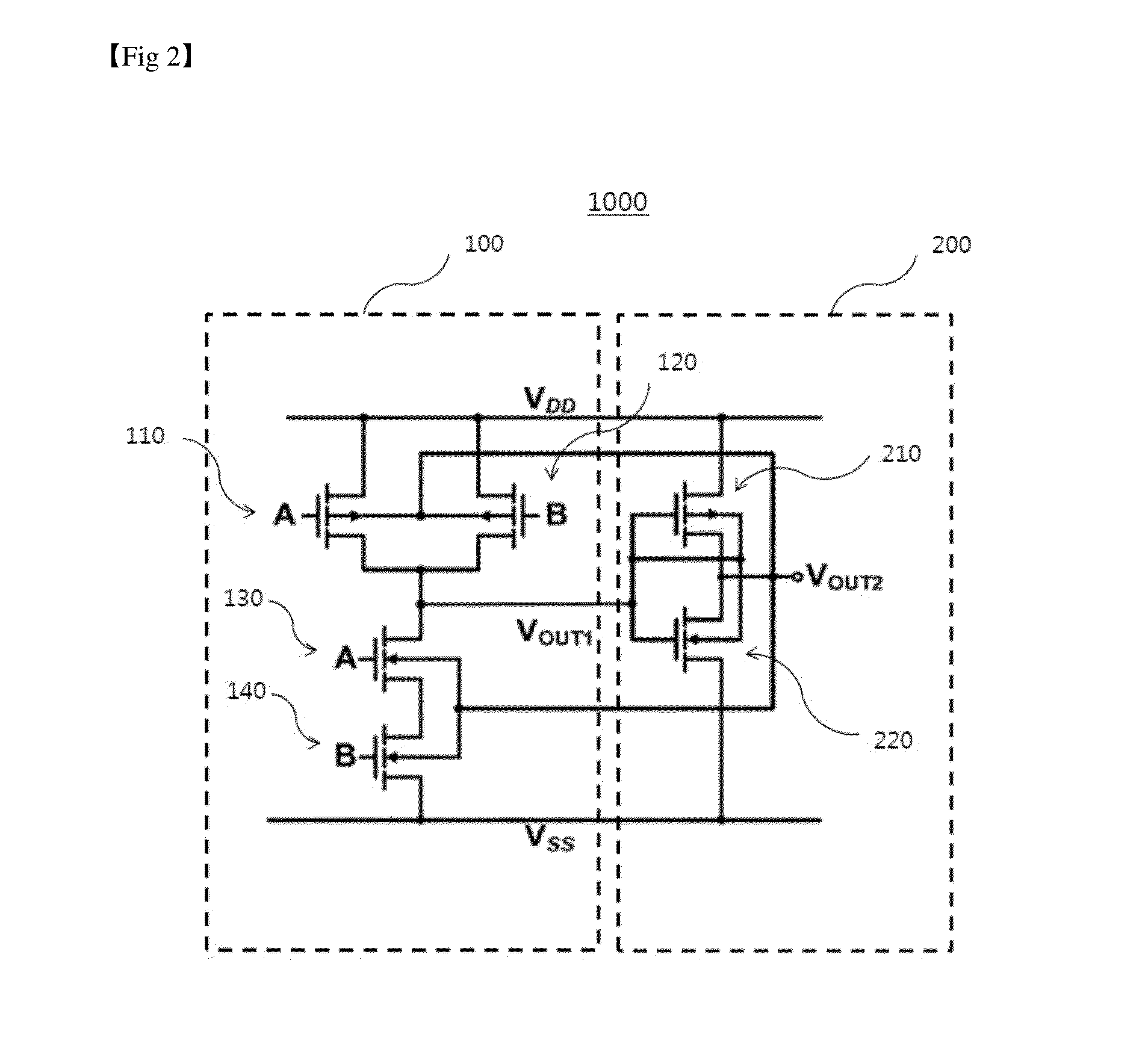
Logic gate using schmitt trigger circuit

a logic gate and trigger circuit technology, applied in logic circuit coupling/interface arrangement, power consumption reduction, pulse technique, etc., can solve the problems of signal delay difference between different signal transmission paths and conventional technology has a lot of problems, so as to improve noise immunity of low power circuits, improve integration, and reduce power consumption

Active Publication Date: 2015-10-22
RES & BUSINESS FOUND SUNGKYUNKWAN UNIV
View PDF5 Cites 4 Cited by
  • Summary
  • Abstract
  • Description
  • Claims
  • Application Information

AI Technical Summary

Benefits of technology

The patent describes a logic gate that can make low power circuits better at fighting noise, make them more efficient, and use less power.

Problems solved by technology

In order to reduce an area of a circuit due to a degree of integration, technology of inserting a buffer using a Schmitt trigger into the conventional circuit has been largely studied, but the technology tends to cause a signal delay difference between different signal transmission paths.
Consequently, the conventional technology has a lot of problems from the point of view of a low power design and also the degree of integration.

Method used


Image

  • Logic gate using schmitt trigger circuit
  • Logic gate using schmitt trigger circuit
  • Logic gate using schmitt trigger circuit

Examples


Embodiment Construction

[0042]The following detailed description is provided to assist the reader in gaining a comprehensive understanding of the methods, apparatuses, and / or systems described herein. However, various changes, modifications, and equivalents of the systems, apparatuses and / or methods described herein will be apparent to one of ordinary skill in the art. The progression of processing steps and / or operations described is an example; however, the sequence of and / or operations is not limited to that set forth herein and may be changed as is known in the art, with the exception of steps and / or operations necessarily occurring in a certain order. Also, descriptions of functions and constructions that are well known to one of ordinary skill in the art may be omitted for increased clarity and conciseness.

[0043]The features described herein may be embodied in different forms, and are not to be construed as being limited to the examples described herein. Rather, the examples described herein have bee...


PUM


Abstract

Logic gates using Schmitt trigger circuits are provided. An AND gate using the Schmitt trigger circuit includes: a NAND gate configured to receive two input signals, perform a NAND logic operation, and output a first output signal; and a DTMOS inverter configured to invert the first output signal, and output the inverted first output signal as a second output signal, and a threshold voltage of the NAND gate is controlled using the second output signal. A OR gate using the Schmitt trigger circuit includes: a NOR gate configured to receive two input signals, perform a NOR logic operation, and output a first output signal; and a DTMOS inverter configured to invert the first output signal, and output the inverted first output signal as a second output signal, and a threshold voltage of the NOR gate is controlled using the second output signal.

Description

CROSS-REFERENCE TO RELATED APPLICATION[0001]This application claims the benefit under 35 USC 119(a) of Korean Patent Application No. 10-2014-0045189, filed on Apr. 16, 2014, the entire disclosure of which is incorporated herein by reference for all purposes.BACKGROUND[0002]1. Field[0003]The following description relates to a Schmitt trigger circuit, and to a logic gate using a Schmitt trigger circuit.[0004]2. Description of Related Art[0005]A Schmitt trigger circuit is a circuit outputting “0” or “1” by controlling a threshold voltage used as a reference voltage in which an output signal is changed according to a change of an input signal, and making different threshold voltages according to the change of the input signal.[0006]The circuit performs an operation of increasing an output voltage when an input voltage is greater than a predetermined value, and of decreasing the output voltage when the output voltage is equal to or smaller than the predetermined value. The Schmitt trigge...

Claims


Application Information

Patent Timeline
IPC IPC(8): H03K19/00H03K3/037H03K3/013H03K19/20H03K19/0185
CPCH03K19/0016H03K19/20H03K3/0377H03K3/013H03K19/018507H03K3/3565H03K19/018521
Inventor KIM, SO YOUNGKIM, KYUNG SOONAH, WAN SOO
Owner RES & BUSINESS FOUND SUNGKYUNKWAN UNIV
Learn More