
Guide system for solar panels

Active Publication Date: 2015-10-22
SAINT AUGUSTIN CANADA ELECTRIC
View PDF8 Cites 7 Cited by
  • Summary
  • Abstract
  • Description
  • Claims
  • Application Information

AI Technical Summary

Benefits of technology

The patent is about a device called the torsion tube, which is used to guide the movement of a mechanism. The design allows for higher precision rotational movements by decoupling the weight of the support arms and sunlight-absorbing devices from the torque load on the torsion tube. Additionally, the dimensions of the torsion tube and housing can be customized for better economization of fabrication and material costs. The technical effects of the patent are improved precision and cost reduction for guiding mechanisms.

Problems solved by technology

Using two motors for one axis, however, not only is more expensive than, for example, just using one, but also the guide system becomes more complex and, therefore, more vulnerable to technical failure.
This design, however, is only suited to hold and move rather small and light sunlight-absorbing devices, which do not put too much torsion and load stress on the U-shaped torque transmitting element, which significantly can worsen the precision of the tracking.
This design can lead to a disadvantageous distribution of load and torque within the system, in particular, for very large and heavy sunlight-absorbing surfaces or devices.

Method used


Image

  • Guide system for solar panels
  • Guide system for solar panels
  • Guide system for solar panels

Examples


Embodiment Construction

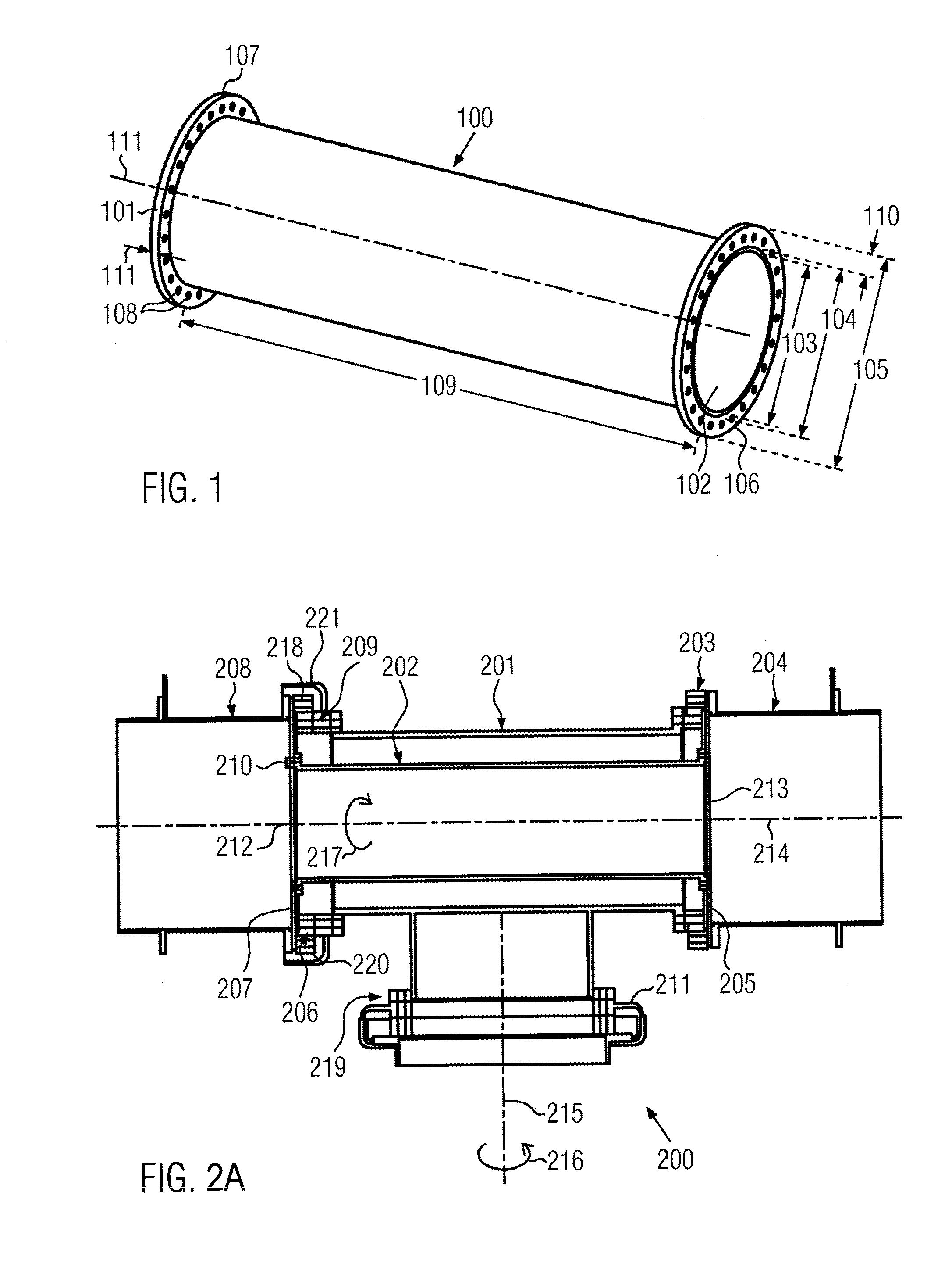
[0044]In FIG. 1, an exemplary torsion tube 100 of a guide system according to the disclosure is shown.

[0045]The torsion tube 100 can have an outer diameter 104 of up to 320 mm or more, and / or a thickness, i.e., the difference between outer diameter 104 and inner diameter 103, of up to 12 mm or more and / or a length 109 of up to 1200 mm or more, and rims or flanges 106, 107 at both ends 101, 102 with a width 110 of up to 10 mm, 20 mm or more.

[0046]The torsion tube profile can be cylindrical, but other profiles, such as, for example, cubic profiles, are also possible.

[0047]The material of the torsion tube 100 can comprise metal, steel or carbon, with the preferred material being, for example, steel of European structural grades S275 or S355.

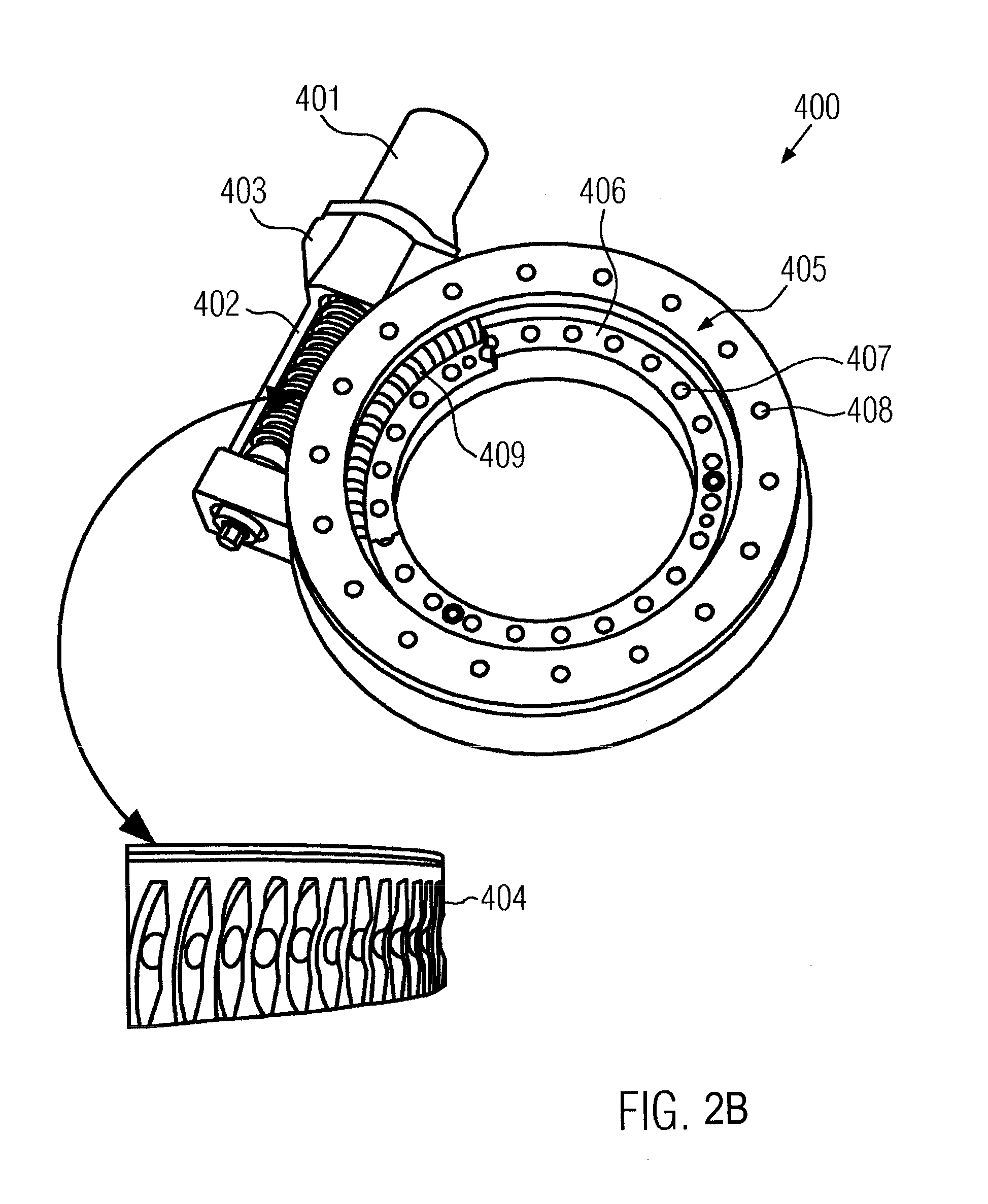
[0048]The rims or flanges 106, 107 can have holes for attaching the torsion tube 100, for example, to a gear unit and / or a turnable disc and / or support arm by, for example, by means of screws or bolts, as shown further down in FIGS. 2A, 2B, and 3. H...


PUM


Abstract

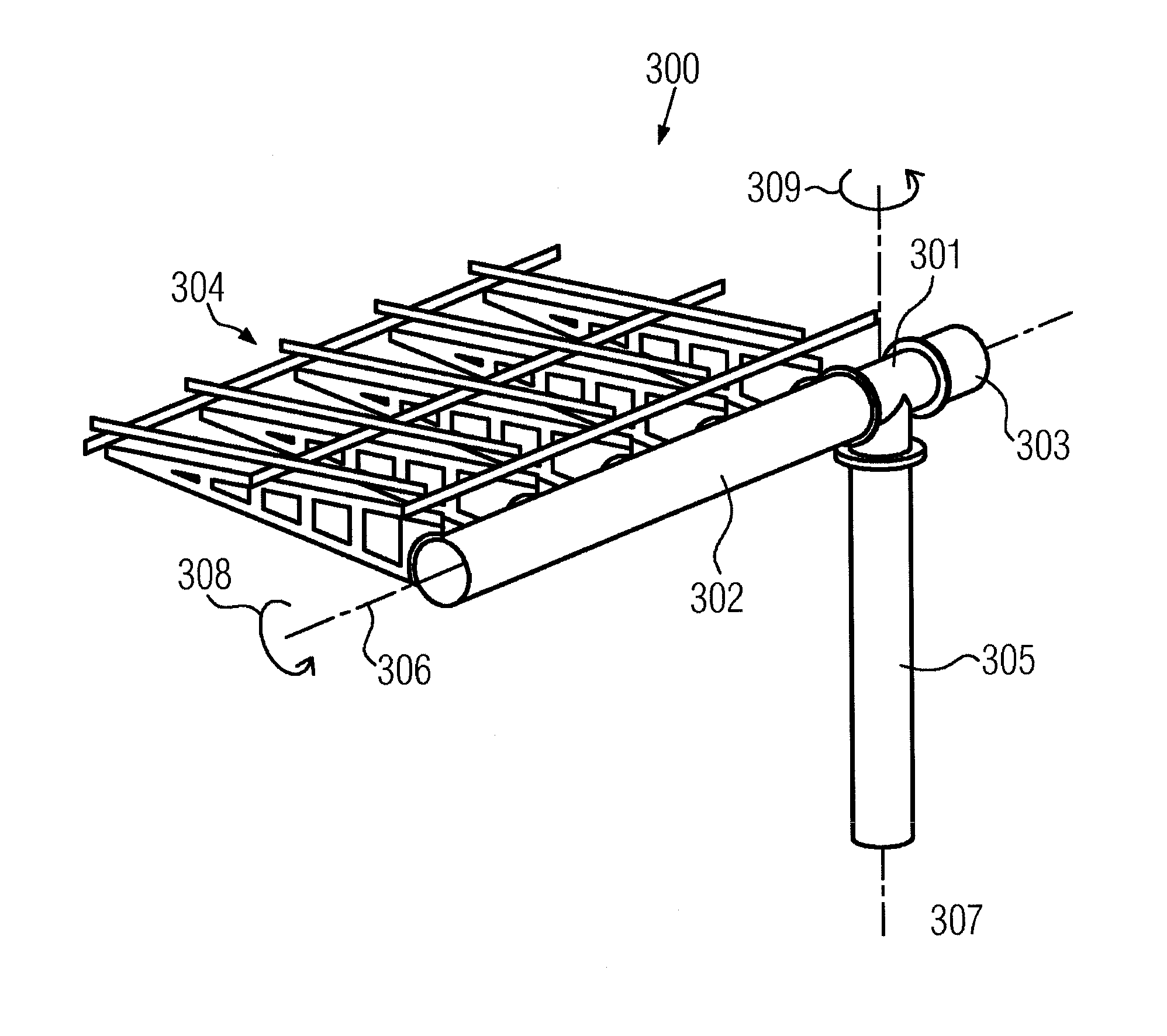
The disclosure relates to a guide system for holding and moving sunlight-absorbing devices, in particular, solar panels or concentrated photovoltaic modules, about an azimuth axis and an elevation axis, comprising a housing, at least one azimuth drive, at least one azimuth gear unit, the azimuth drive being configured for driving the azimuth gear unit for a rotational movement about the azimuth axis, at least one elevation drive, at least one elevation gear unit, the elevation drive being configured for driving the elevation gear unit for a rotational movement about the elevation axis, and wherein the elevation gear unit is connected to a first end of a torsion tube, and the torsion tube is turnably mounted inside the housing along the elevation axis, wherein the torsion tube is supported by at least two bearings, preferably one at each end of the torsion tube, and wherein the second end of the torsion tube is configured to receive and connect to a support arm for carrying / supporting one or more of the sunlight-absorbing devices, and the torsion tube further being configured to transmit torque from the elevation gear unit to the support arm.

Description

CROSS-REFERENCE TO RELATED APPLICATIONS[0001]This application is a national phase entry under 35 U.S.C. §371 of International Patent Application PCT / EP2013 / 073030, filed Nov. 5, 2013, designating the United States of America and published in English as International Patent Publication WO 2014 / 072280 A1 on May 15, 2014, which claims the benefit under Article 8 of the Patent Cooperation Treaty and under 35 U.S.C. §119(e) to French Patent Application Serial No. 1260755, filed Nov. 12, 2012, the disclosure of each of which is hereby incorporated herein in its entirety by this reference.TECHNICAL FIELD[0002]This disclosure relates to the field of guide systems for holding and moving sunlight-absorbing devices, in particular, Concentrated Photovoltaic (CPV) modules, wherein sunlight is focused first by an optical system, for example, a lens system, before hitting a photovoltaic cell.BACKGROUND[0003]In order to optimize the efficiency of sunlight-absorbing devices to turn sunlight into ele...

Claims


Application Information

Patent Timeline
IPC IPC(8): H02S20/32F16M11/18F16M11/12H02S40/22
CPCH02S20/32F16M11/126F16M11/18H02S40/22Y02E10/47Y02E10/52F24S30/452F24S2030/134F24S2030/15
Inventor GONZALEZ MORENO, ABEL
Owner SAINT AUGUSTIN CANADA ELECTRIC
Learn More