Rotor of an electric motor and method for producing the rotor

a technology of electric motor and rotor, which is applied in the direction of dynamo-electric machines, magnetic circuit rotating parts, magnetic circuit shape/form/construction, etc., and can solve problems such as detriment to productivity

Active Publication Date: 2015-10-22
VITESCO TECH GERMANY GMBH
View PDF12 Cites 6 Cited by
  • Summary
  • Abstract
  • Description
  • Claims
  • Application Information

AI Technical Summary

Benefits of technology

The present invention provides a rotor for an electric motor and a method of producing it that is easier to produce without using adhesive. The arrangement of channels and webs allows for precise positioning of magnets in the radial direction and on the circumference. The injected plastic presses against the magnets, moving them into their end position, resulting in a more uniform distribution of the magnets and higher tolerances in the laminated armature core. The hold of the magnets on the rotor is increased through an interlock between the magnets and plastic, without significantly increasing the weight or cost of the laminated armature core.

Problems solved by technology

This fixing by an adhesive signifies an additional process step, which has a detrimental effect on productivity.

Method used


Image

  • Rotor of an electric motor and method for producing the rotor
  • Rotor of an electric motor and method for producing the rotor
  • Rotor of an electric motor and method for producing the rotor

Examples


Embodiment Construction

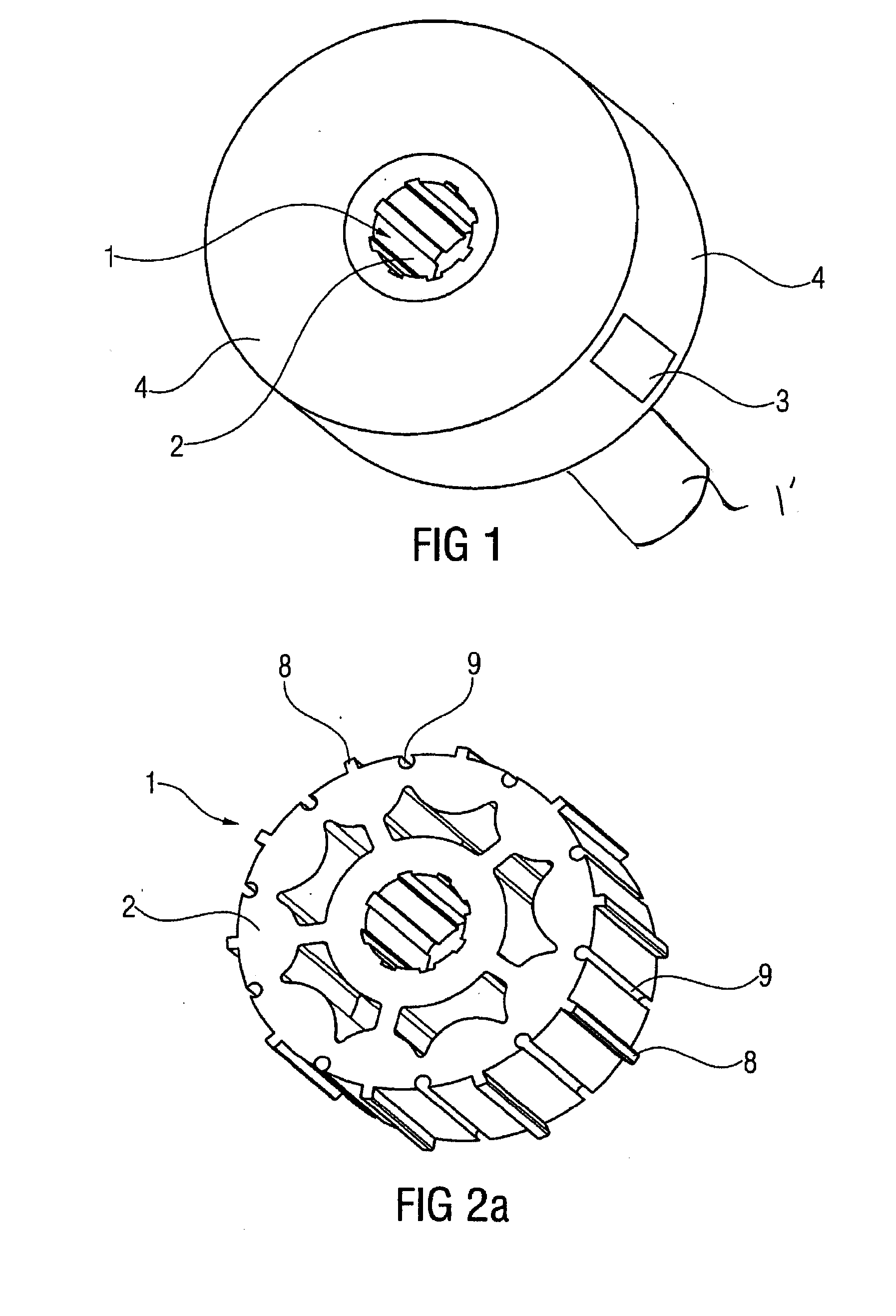
[0021]FIG. 1 shows a rotor of an electric motor used in a fuel pump or an actuating element. A laminated armature core 1 sits on the shaft 1′ of the rotor and consists of a plurality of stamped metal sheets 2, which are connected to form the laminated armature core 1. Magnets 3 are distributed around the outer lateral surface of the laminated armature core 1. The laminated armature core 1 and magnets 3 are overmolded with plastic 4 and together, as a homogeneous body, form the rotor. The magnets can be hard ferrite magnets or neodymium magnets.

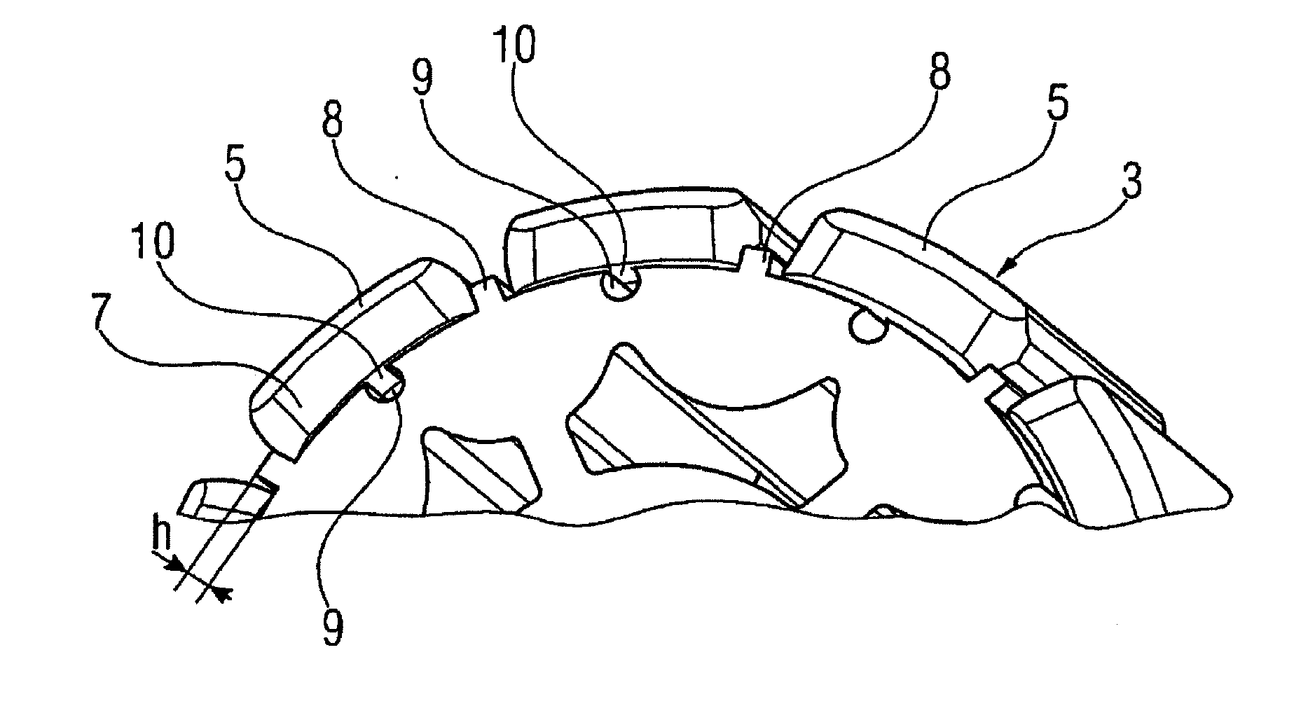
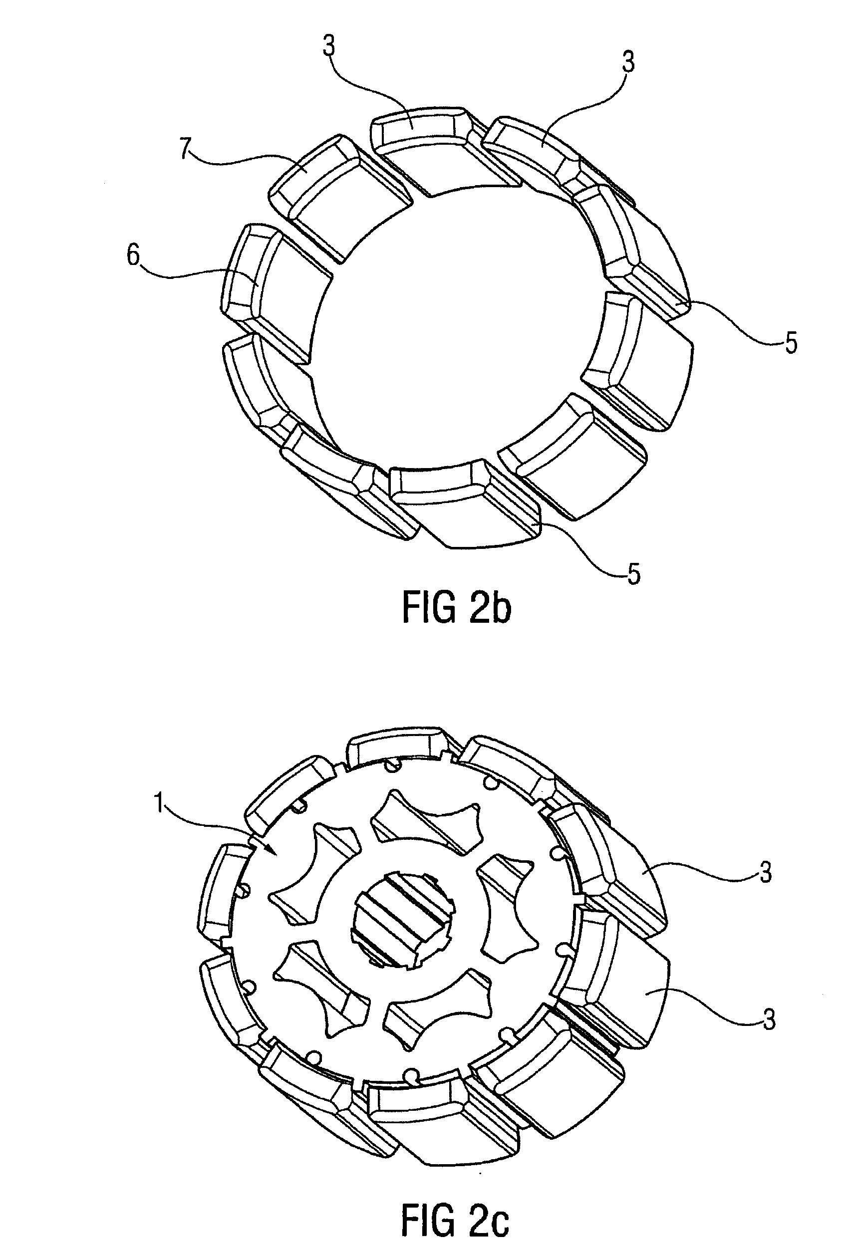
[0022]FIG. 2a shows the laminated armature core 1, consisting of the stamped metal sheets 2 and the magnets 3 in an exploded illustration. The magnets 3 as illustrated in FIGS. 2b and 2c and 3, have, at their radially outer edges 5 and the radially inner edges 6 of the end faces 7, chamfers 10, which ensure an interlocked bond between magnet 3 and plastic 4 during the overmolding with the plastic 4. The plastic 4 may be polyoxymethylene or pol...


PUM


Abstract

A rotor of an electric motor includes a laminated armature core, a shaft, magnets arranged on the circumference of the laminated armature core, and a plastic overmold. The laminated armature core has at least one associated channel on the circumference of the laminated armature core for each magnet. The channels extend parallel to the shaft, and the laminated armature core has radially oriented webs on the circumference. The webs (8) extend parallel to the shaft and a magnet (9) is arranged between each pair of webs (8), and the plastic overmold (4) encloses the laminated armature core (1) and the magnets (3) to such an extent that only the radial outer face of the magnets (3) is free of plastic (4).

Description

CROSS-REFERENCE TO RELATED APPLICATIONS[0001]This is a U.S. national stage of application No. PCT / EP2013 / 074024, filed on 18 Nov. 2013, which claims priority to the German Application No. DE 10 2012 221 422.4 filed 23 Nov. 2012, the content of both incorporated herein by reference.BACKGROUND OF THE INVENTION[0002]1. Field of the Invention[0003]The invention relates to a rotor of an electric motor, comprising a laminated armature core, a shaft, magnets arranged on the circumference of the laminated armature core, and a plastic overmold. The invention also relates to a method for producing the rotor.[0004]2. Related Art[0005]Electric motor rotors of this type are used, for example, in fuel pumps or actuating elements. In order to achieve a high degree of efficacy of the electric motors, the magnetic flux must be as high as possible. This presupposes that the magnets are arranged exactly in their predefined position on the rotor and cooperate as optimally as possible with the stator of...

Claims


Application Information

Patent Timeline
Patent Type & Authority Applications(United States)
IPC IPC(8): H02K1/28H02K15/12H02K1/27H02K15/10
CPCH02K1/28H02K1/278H02K15/12H02K15/10H02K15/03
Inventor SIEBALD, KURT
Owner VITESCO TECH GERMANY GMBH
Why Eureka
Try Eureka