Fixing structure for heat exchanger
a technology of fixing structure and heat exchanger, which is applied in the direction of indirect heat exchangers, heat exchange apparatus safety devices, light and heating apparatus, etc., can solve the problems of reducing productivity, increasing the number of components producing the evaporator, and increasing the number of processes for manufacturing the evaporator, so as to reduce the noise caused by vibration transmitted to the case from the heat exchanger, the effect of simple configuration
- Summary
- Abstract
- Description
- Claims
- Application Information
AI Technical Summary
Benefits of technology
Problems solved by technology
Method used
Image
Examples
first embodiment
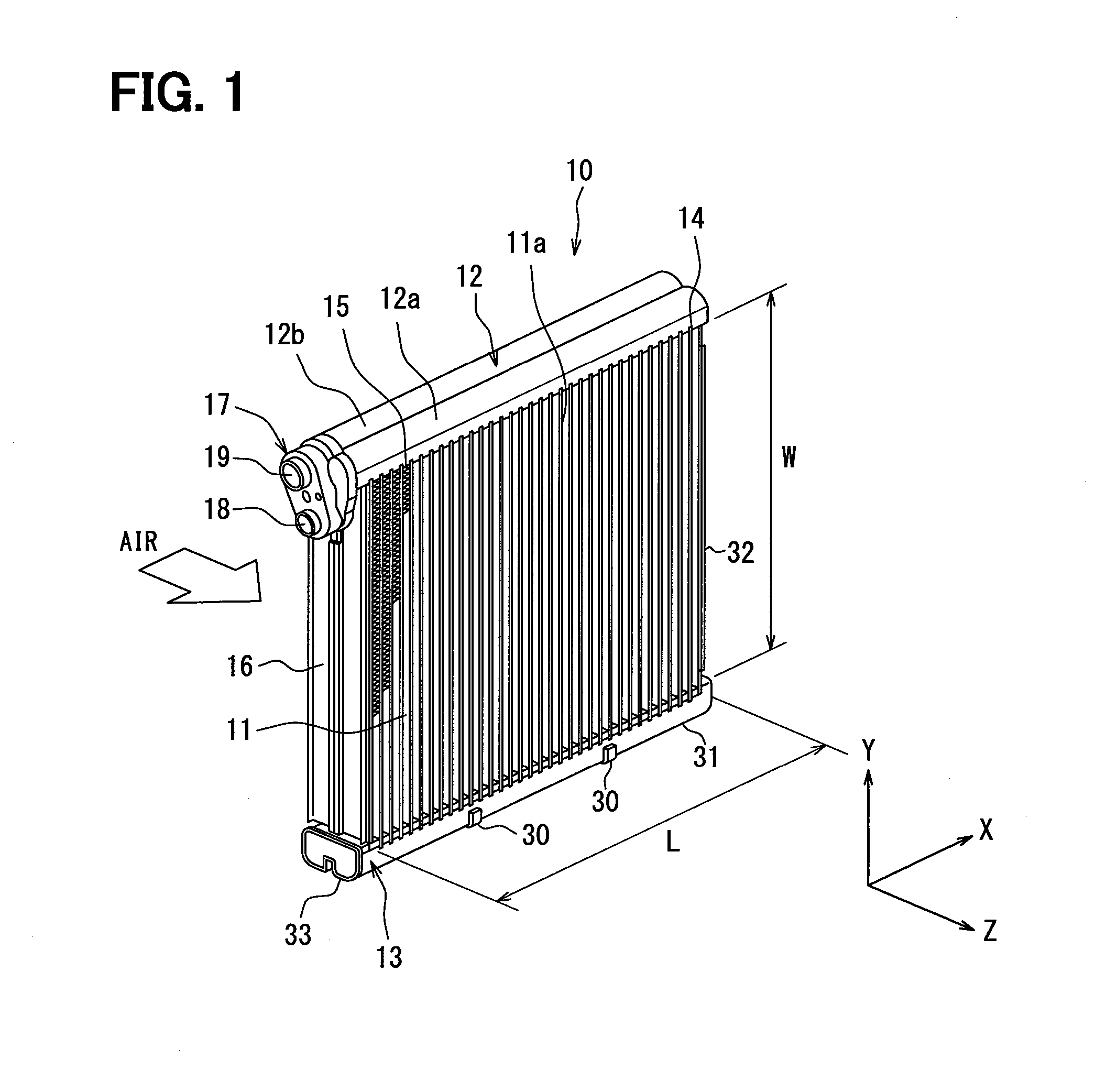
[0023]A first embodiment of the present disclosure will be described with reference to FIGS. 1 to 6. An evaporator 10 is a heat exchanger arranged in a refrigeration cycle not shown, in which refrigerant is compressed by a compressor to have high temperature and high pressure and is cooled by a radiator through heat radiation. Further, refrigerant is depressurized by a depressurizing device to have low temperature and low pressure, and the refrigerant is evaporated by the evaporator 10. As illustrated in FIG. 1, the evaporator 10 according to this embodiment includes a core portion 11, an upper tank unit 12, and a lower tank unit 13. The respective components are brazed to each other.
[0024]The core portion 11 is configured by alternately stacking multiple flat tubes 14 and multiple corrugated fins 15 on each other. A side plate 16 is arranged outside of the outermost corrugated fins 15 on both sides in a stacking direction thereof (X-direction in FIG. 1). A refrigerant which is an i...
second embodiment
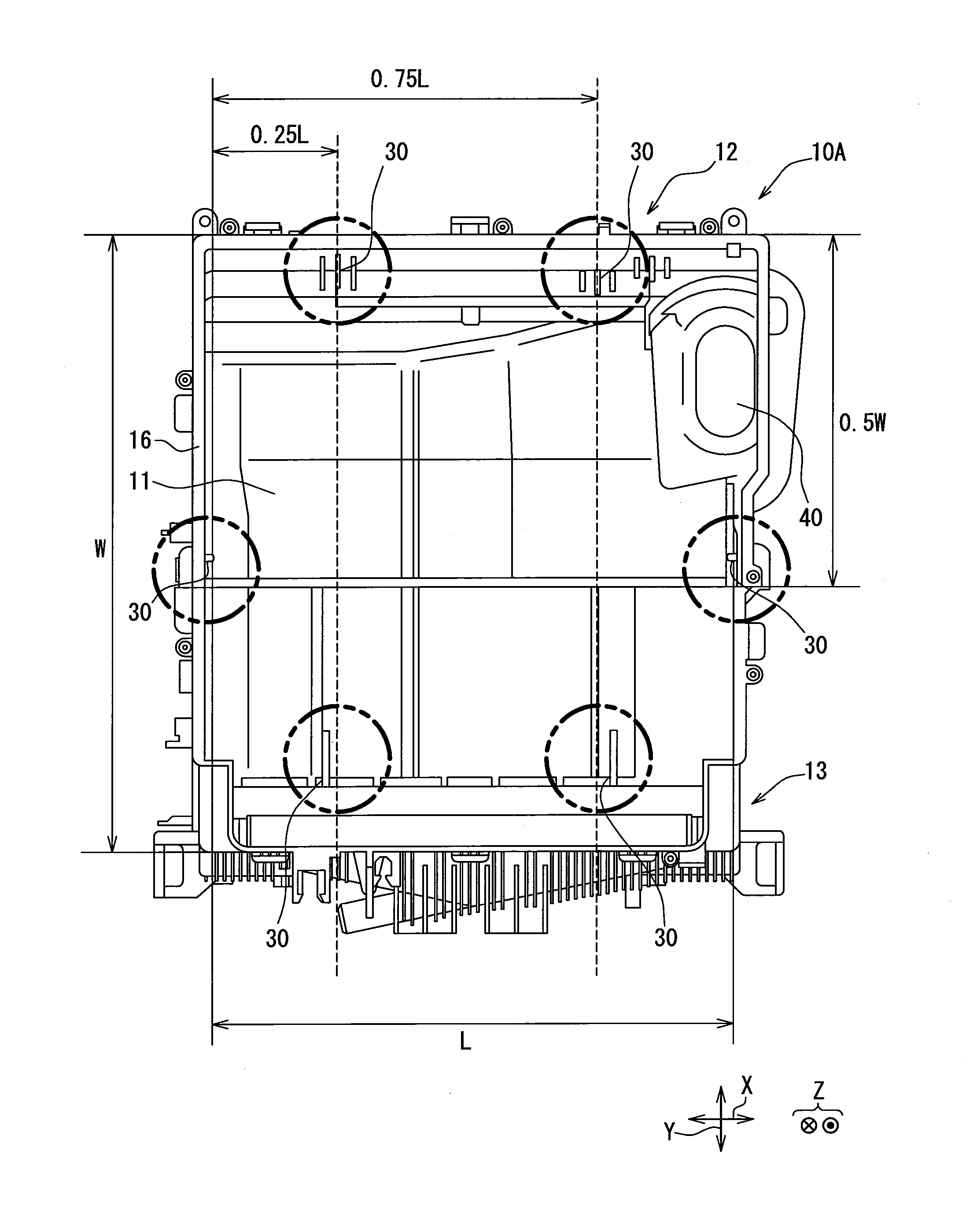
[0056]A second embodiment of the present disclosure will be described with reference to FIGS. 7 and 8. FIG. 7 illustrates an air conditioning apparatus for a vehicle, and an evaporator 10A is illustrated as an element configuring the air conditioning apparatus. The evaporator 10A configuring the air conditioning apparatus illustrated in FIG. 7 is integrally provided with an expansion valve 40. The evaporator 10A is connected to an outflow side of the expansion valve 40 in a refrigeration cycle device, and a refrigerant depressurized by the expansion valve 40 flows into the evaporator 10A. In the present embodiment, the fixing portion 30 is disposed at six locations. The respective fixing portion 30 is configured by a protrusion portion, similarly to the first embodiment.
[0057]As illustrated in FIG. 7, the fixing portions 30 are disposed in each of an upper tank unit 12 and a lower tank unit 13 at positions apart by 0.25 L±0.05 L and positions apart by 0.75 L±0.05 L from an end of a ...
third embodiment
[0059]A third embodiment of the present disclosure will be described with reference to FIG. 9. In FIG. 9, a configuration of a fixing portion 30B is different from that in the evaporator 10 of the first embodiment. The fixing portion 30B of the evaporator 10B according to this embodiment is defined by a protrusion portion protruding outward from a lower tank unit 13 as described above. Further, the protrusion portion is covered with an elastic member, for example, an antivibration rubber.
[0060]The fixing portion 30B is configured integrally with the protrusion portion and the elastic member, thereby being capable of surely bringing the elastic member in contact with the air conditioning case. With the above configuration, the vibration transmitted from the fixing portion 30B to the air conditioning case can be further attenuated.
PUM
 Abstract
Description
Claims
Application Information
 - R&D
- Intellectual Property
- Life Sciences
- Materials
- Tech Scout
- Unparalleled Data Quality
- Higher Quality Content
- 60% Fewer Hallucinations
Browse by: Latest US Patents, China's latest patents, Technical Efficacy Thesaurus, Application Domain, Technology Topic, Popular Technical Reports.
© 2025 PatSnap. All rights reserved.Legal|Privacy policy|Modern Slavery Act Transparency Statement|Sitemap|About US| Contact US: help@patsnap.com


