
Substrate structure and manufacturing method thereof

a technology of substrate and manufacturing method, applied in the direction of laminated printed circuit boards, printed circuit non-printed electric components association, circuit masks, etc., can solve the problems of substrate being easily broken or having wiring defects, and the substrate being easily separated from the carrier during the process, so as to improve the bonding strength and easy to separate

Inactive Publication Date: 2015-10-15
SUBTRON TECH
View PDF2 Cites 2 Cited by
  • Summary
  • Abstract
  • Description
  • Claims
  • Application Information

AI Technical Summary

Benefits of technology

The invention provides a substrate structure and manufacturing method that improves the bonding strength between a substrate and a carrier while making it easy to separate them. This structure also provides a sensing space for a sensing element of a package structure and satisfies the need for filling paste or liquid and ventilation of a package element. The manufacturing process involves laminating the substrate to the carrier to enhance the bonding strength between them and facilitate separation without damaging the substrate. This improves the yield rate of the manufacturing process.

Problems solved by technology

However, in the chip packaging process, the miniaturized substrates may be broken easily or have defects in wiring.
However, when a substrate is separated from the carrier, some adhesive material may remain on the back surface of the substrate due to the overly strong adhesive force of the release layer.
If a release layer having a weaker adhesive force is used to avoid leaving the adhesive material on the substrate or to separate the substrate from the carrier easily, the issue that the substrate may be separated from the carrier during the process arises.

Method used


Image

  • Substrate structure and manufacturing method thereof
  • Substrate structure and manufacturing method thereof
  • Substrate structure and manufacturing method thereof

Examples


Embodiment Construction

[0032]Reference will now be made in detail to the present preferred embodiments of the invention, examples of which are illustrated in the accompanying drawings. Wherever possible, the same reference numbers are used in the drawings and the description to refer to the same or like parts.

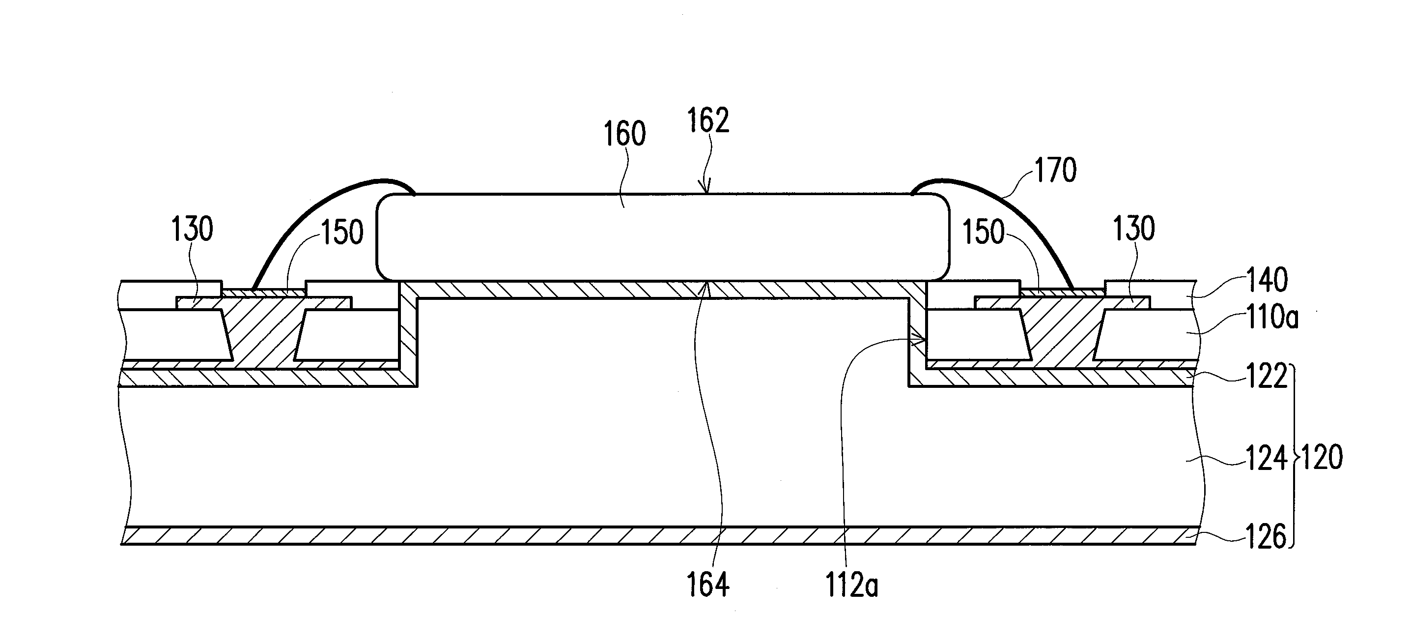
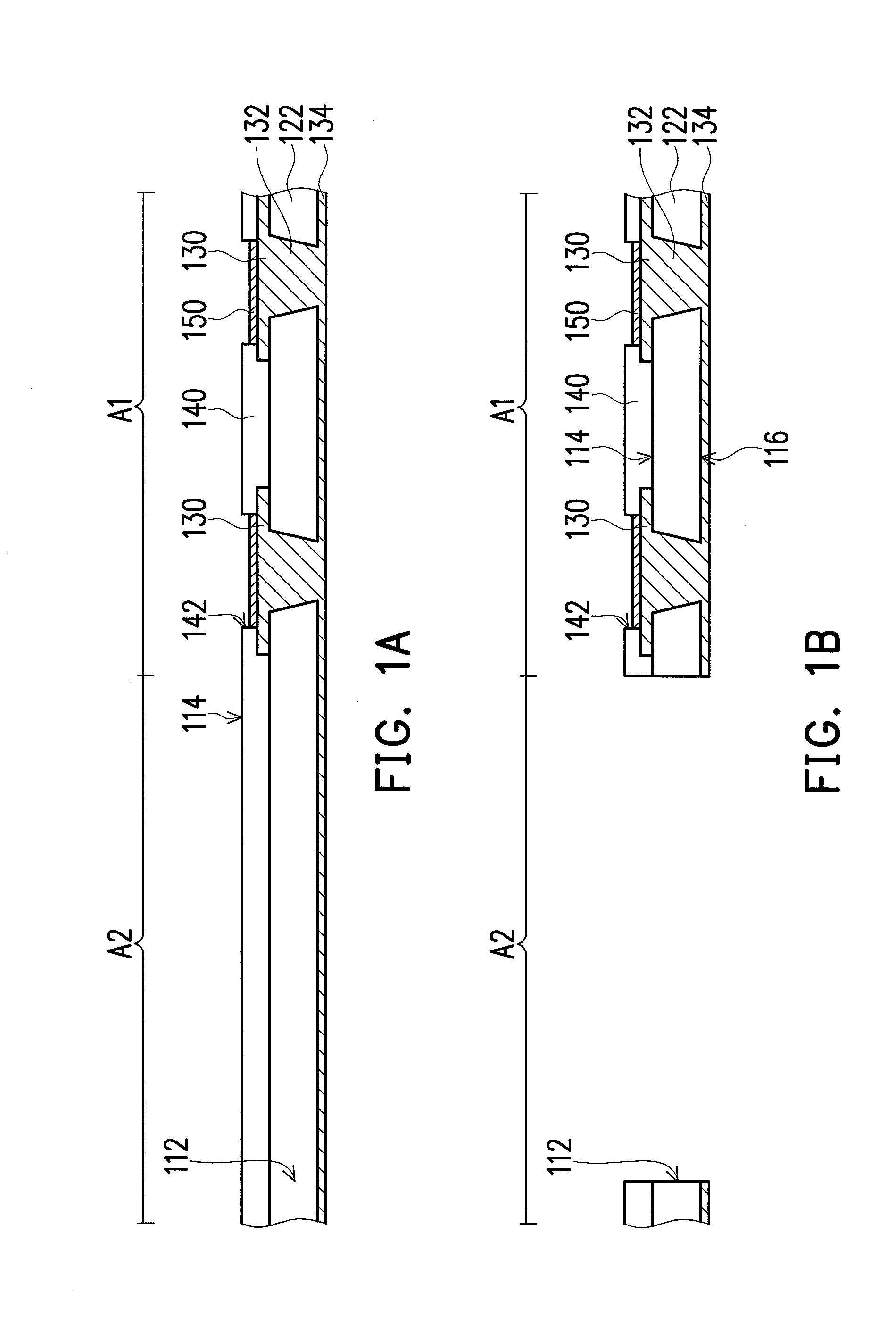
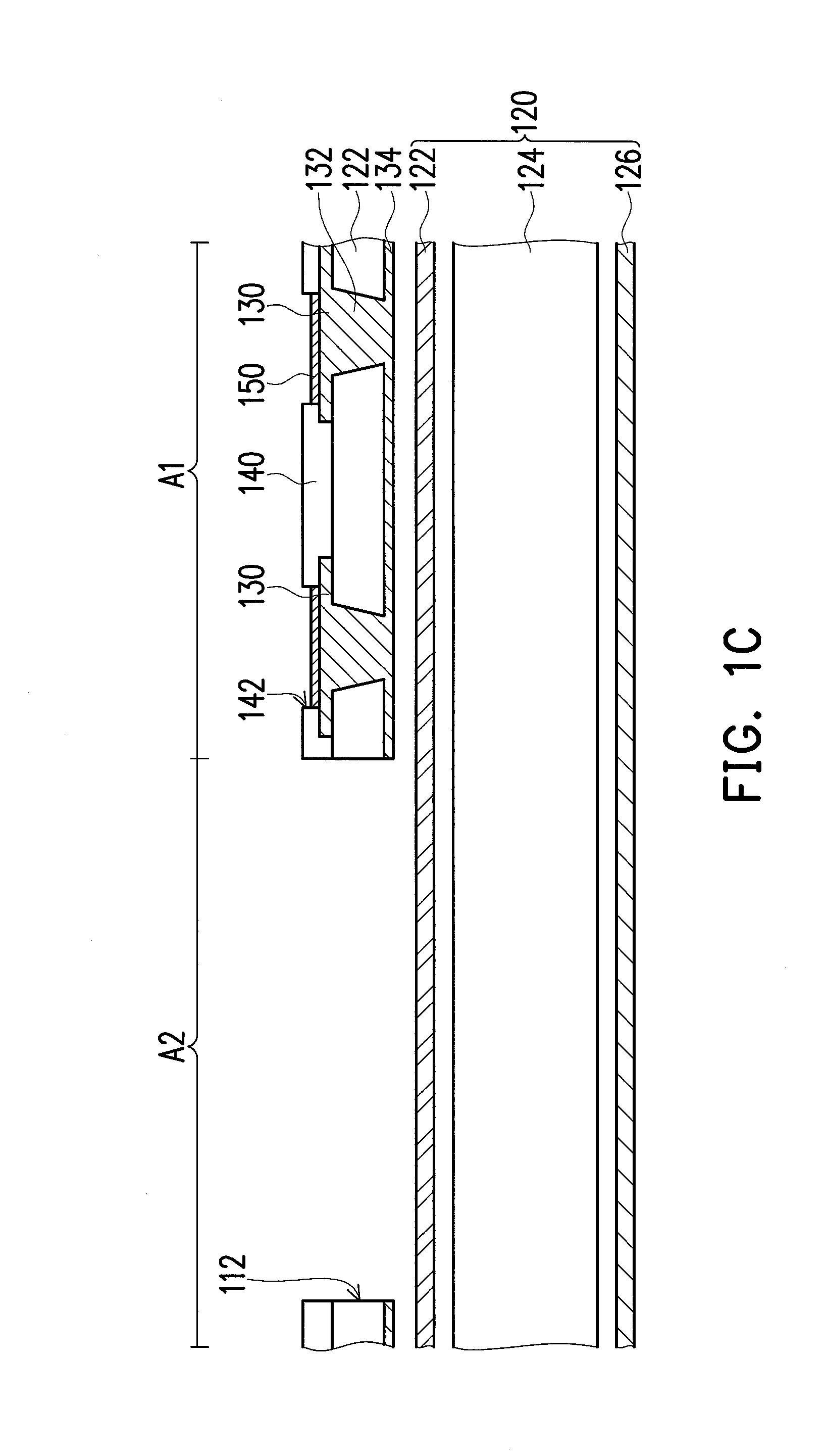
[0033]FIGS. 1A to 1D are cross-sectional schematic views illustrating the processes of a manufacturing method of a substrate structure according to an embodiment of the invention. FIG. 2 is a top schematic view illustrating a substrate according to an embodiment of the invention. Referring to FIGS. 1A and 2, the manufacturing method of the substrate structure of this embodiment includes steps as follows. First of all, as shown in FIG. 1A, a substrate 110 is provided. In this embodiment, the substrate may be a single-layer circuit board or a multi-layer circuit board. In addition, the substrate 110 may include a packaging region A1 and a peripheral region A2, as shown in FIG. 1A. In this embodiment, t...


PUM

PropertyMeasurementUnit
bonding strengthaaaaaaaaaa
rigidityaaaaaaaaaa
adhesive forceaaaaaaaaaa

Abstract

A substrate structure including a carrier and a substrate is provided. The carrier includes a release layer, a dielectric layer and a metal layer. The dielectric layer is disposed between the release layer and the metal layer. The substrate includes a packaging region and a peripheral region. The peripheral region is connected to the packaging region and surrounds the packaging region. The peripheral region or the packaging region has a plurality of through holes. The substrate is disposed on the carrier. The release layer is located between the substrate and the dielectric layer. The release layer and the dielectric layer are filled in the through hole such that the substrate is separably attached to the carrier.

Description

CROSS-REFERENCE TO RELATED APPLICATION[0001]This application claims the priority benefit of Taiwan application serial no. 103113683, filed on Apr. 15, 2014. The entirety of the above-mentioned patent application is hereby incorporated by reference herein and made a part of this specification.BACKGROUND OF THE INVENTION[0002]1. Field of the Invention[0003]The invention relates to a substrate structure, and particularly relates to a substrate structure having a preferable bonding strength or capable of providing a sensing space required by a sensing element of a package structure and meeting the need for filling paste or liquid and the need for ventilation of a package element.[0004]2. Description of Related Art[0005]Circuit substrates are used in a variety of electronic products for electrical signal transmission, power supply, and ground connection. Through miniaturization of electronic products, circuit substrates are also developed in the tendency of being more compact and having ...

Claims


Application Information

Patent Timeline
Patent Type & Authority Applications(United States)
IPC IPC(8): H05K1/11H05K3/32B32B37/26H05K13/04B32B37/24B32B38/04H05K1/18H05K3/00
CPCH05K1/115B32B2457/08H05K1/111H05K3/32H05K3/0073H05K3/0058H05K13/046H05K3/0094B32B37/24B32B38/04B32B37/26H05K2203/0221H05K2203/0548H05K2203/06B32B2038/047B32B2307/202B32B2037/268B32B2307/204H05K1/181H01L2224/48091H01L2224/48227H01L2224/85005H01L2924/15151H01L2924/15313H05K3/007H05K3/3421H05K2201/0154H05K2201/09072H05K2203/0156H01L2924/00014
Inventor HUANG, YU-CHILIN, KUO-TUNG
Owner SUBTRON TECH
Learn More