Supplemental air cooling system and air pressure oil sealing system for electrical turbocompound machine

a turbocompound machine and air cooling system technology, applied in the direction of machines/engines, mechanical equipment, liquid fuel engines, etc., can solve the problems of unoptimized ability of air cooling systems and liquid cooling systems to adequately cool electric motors

Active Publication Date: 2015-10-08
BORGWARNER INC
View PDF2 Cites 10 Cited by
  • Summary
  • Abstract
  • Description
  • Claims
  • Application Information

AI Technical Summary

Benefits of technology

The invention is an electrically assisted turbocharger with an air cooling system for the electric motor using ducts for directing cooling air inside the motor chamber. The cooling air flows in an axial direction from the inlet to the outlet, cooling the motor and then being directed out of the motor chamber. The technical effect is improved cooling efficiency for the electric motor, which leads to improved performance and durability of the turbocharger.

Problems solved by technology

However, under certain operating conditions, it is recognized that the liquid cooling system may not adequately cool the electric motor.
Known air cooling systems art are not optimal in terms of the ability to supplement a liquid cooling system in an electrically assisted turbocharger.

Method used


Image

  • Supplemental air cooling system and air pressure oil sealing system for electrical turbocompound machine
  • Supplemental air cooling system and air pressure oil sealing system for electrical turbocompound machine
  • Supplemental air cooling system and air pressure oil sealing system for electrical turbocompound machine

Examples


Embodiment Construction

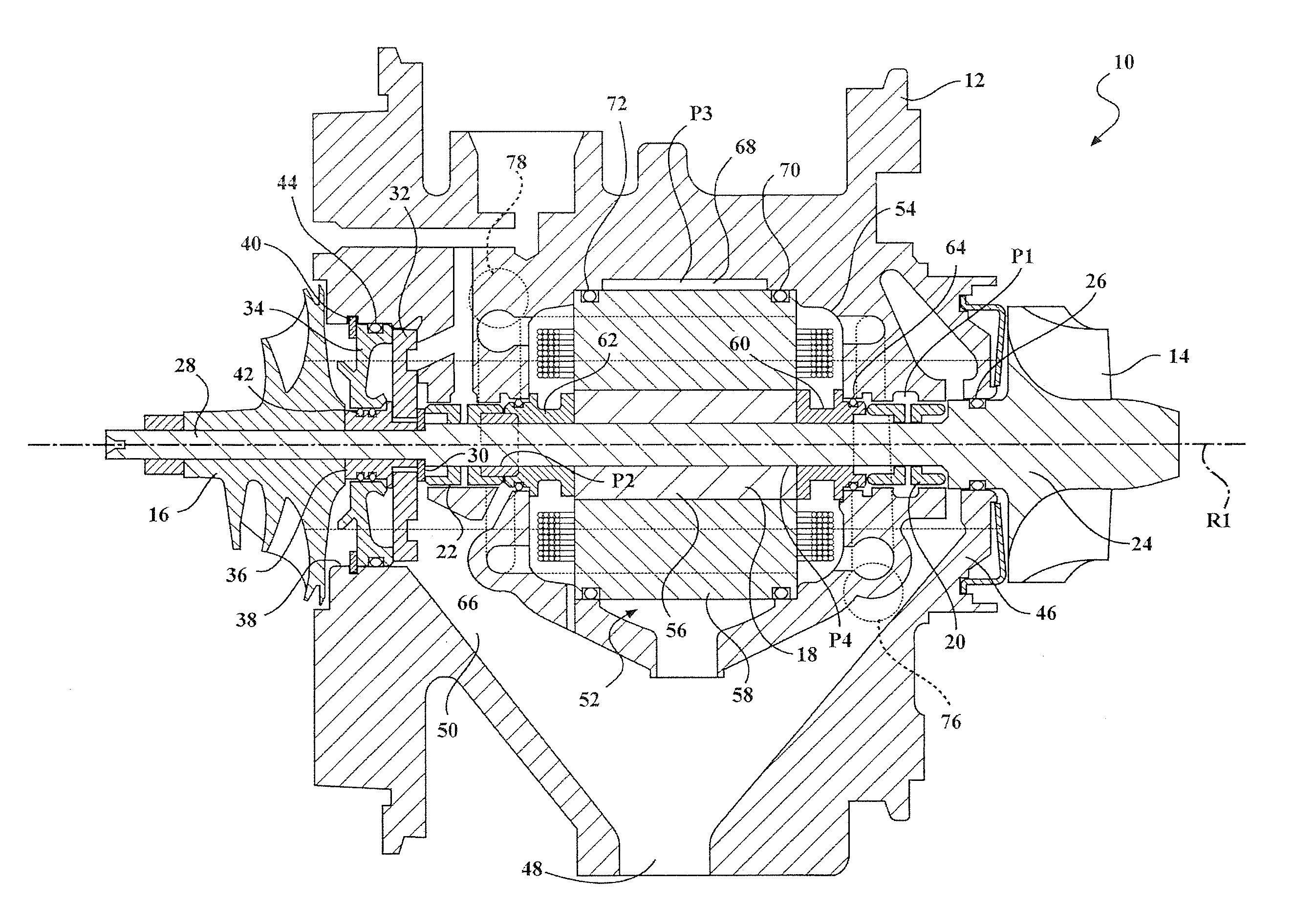
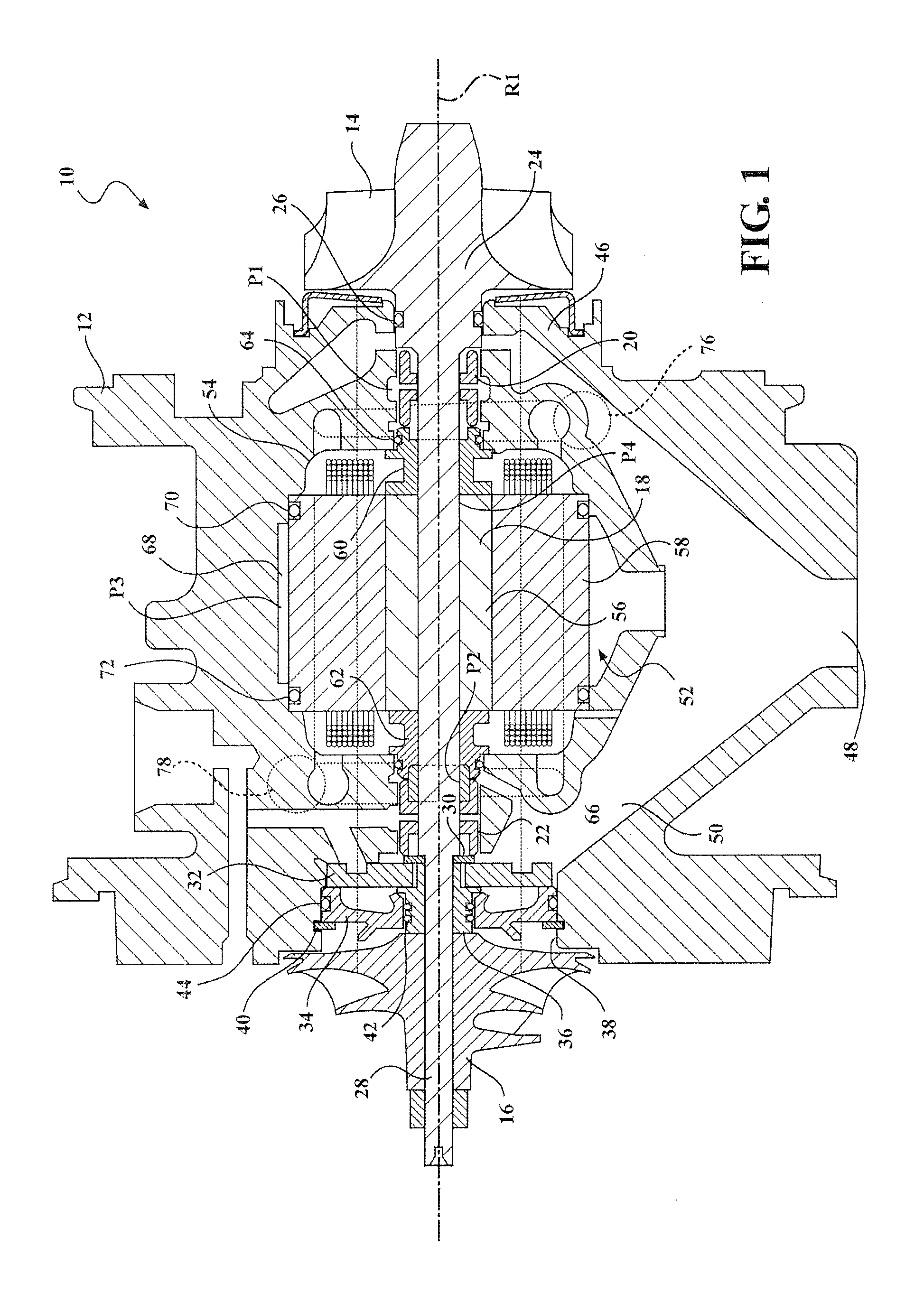
[0020]Referring to the Figures, a portion of a turbocharger is illustrated generally at 10 in FIG. 1. The turbocharger 10 includes a bearing housing 12 coupled between a turbine stage and a compressor stage. The turbine stage includes a turbine wheel 14 disposed within a turbine housing (not shown) and the compressor stage includes a compressor impeller 16 disposed within a compressor housing (not shown). The turbine wheel 14 is rotatably driven by an inflow of exhaust gas supplied from an engine exhaust manifold. After driving the turbine wheel 14, the exhaust gas is discharged from the turbine housing through a central exit pipe or exducer. A shaft 18 is rotatably supported in the bearing housing 12 and connects the turbine wheel 14 to the compressor impeller 16 such that rotation of the turbine wheel 14 causes rotation of the compressor impeller 16. The shaft 18 connecting the turbine wheel 14 and the compressor impeller 16 defines an axis of rotation R1. As the compressor impell...


PUM


Abstract

An electrically assisted turbocharger (10) includes an air cooling system for cooling an electric motor (52) housed within a motor chamber (54) in a bearing housing (12). An inlet volute (76) is formed in the bearing housing (12) on a first side of the electric motor (52) and an outlet volute (78) is formed in the bearing housing (12) on a second side of the electric motor (52) opposite from the inlet volute (76). The inlet volute (76) accelerates cooling air that is fed into the inlet volute (76) and directs the cooling air into the motor chamber (54). The cooling air travels in an axial direction through the motor chamber (54) from the inlet volute (76) to the outlet volute (78), thereby cooling the electric motor (52). The outlet volute (78) decelerates the cooling air and directs the cooling air out of the motor chamber (54).

Description

CROSS-REFERENCE TO RELATED APPLICATION[0001]This application claims priority to and all the benefits of U.S. Provisional Application No. 61 / 725,150, filed on Nov. 12, 2012, and entitled “Supplemental Air Cooling System And Air Pressure Oil Sealing System For Electrical Turbocompound Machine.”BACKGROUND OF THE INVENTION[0002]1. Field of the Invention[0003]This invention relates to an electrical turbocompound machine for an internal combustion engine. More particularly, this invention relates to an air cooling system for cooling an electric motor within a turbocharger.[0004]2. Description of Related Art[0005]A turbocharger is a type of forced induction system used with internal combustion engines. Turbochargers deliver compressed air to an engine intake, allowing more fuel to be combusted, thus boosting an engine's power density without significantly increasing engine weight. Thus, turbochargers permit the use of smaller engines that develop the same amount of power as larger, normall...

Claims


Application Information

Patent Timeline
IPC IPC(8): F04D29/58F04D29/40F04D17/10
CPCF04D29/582F04D29/403F04D17/10F01D25/12F02B37/10F02B39/10F02C6/12Y02T10/12F04D29/5806
Inventor BUCKING, MICHAEL
Owner BORGWARNER INC
Why Eureka
Try Eureka