
Device for clearing pipe blockage

a technology for clearing pipes and pipes, applied in water installations, cleaning processes and apparatuses, constructions, etc., can solve the problems of difficult effective clearing of blockage using such devices, and the blockage of pipes of toilets, washstands and sinks is often blocked by relatively large foreign objects, so as to reduce the loss of pressure

Inactive Publication Date: 2015-10-01
KIM YONG SOO
View PDF0 Cites 17 Cited by
  • Summary
  • Abstract
  • Description
  • Claims
  • Application Information

AI Technical Summary

Benefits of technology

The invention is a device for clearing blockages in pipes. The device uses an inflatable balloon to clear the blockage by applying sufficient pressure to the inside of the pipe without any loss of pressure. It can maintain the airtight state of the pipe and effectively clear the blocked part of the pipe. The device can also minimize a loss of pressure formed by the pumping unit when in contact with the inside of the pipe. The technical effect of the invention is to provide an efficient and effective solution for clearing blockages in pipes.

Problems solved by technology

Moreover, because a part to drain water adopts a U-shaped trap structure in order to prevent a bad smell from backing up, such a trap structure causes pipe blockage.
In addition to such a structural reason, of course, pipes of the toilets, washstands and sinks are frequently blocked by relatively large-sized foreign matters.
Now, various devices for clearing blockage of a pipe come on the market, but it is difficult to effectively clear the blockage using such devices.
The difficulty in effectively clearing the blocked pipe using the conventional devices may be caused by that sufficient shock or pressure is not applied to the blocked part.
For instance, when a predetermined pressure is applied from the outside to the inside of a toilet in a bathroom, the conventional devices do not provide sufficient airtightness between the outside and the inside of the toilet and cannot effectively generate or transfer pressure to the pipe connected from the inside of the toilet.

Method used


Image

  • Device for clearing pipe blockage
  • Device for clearing pipe blockage
  • Device for clearing pipe blockage

Examples


Embodiment Construction

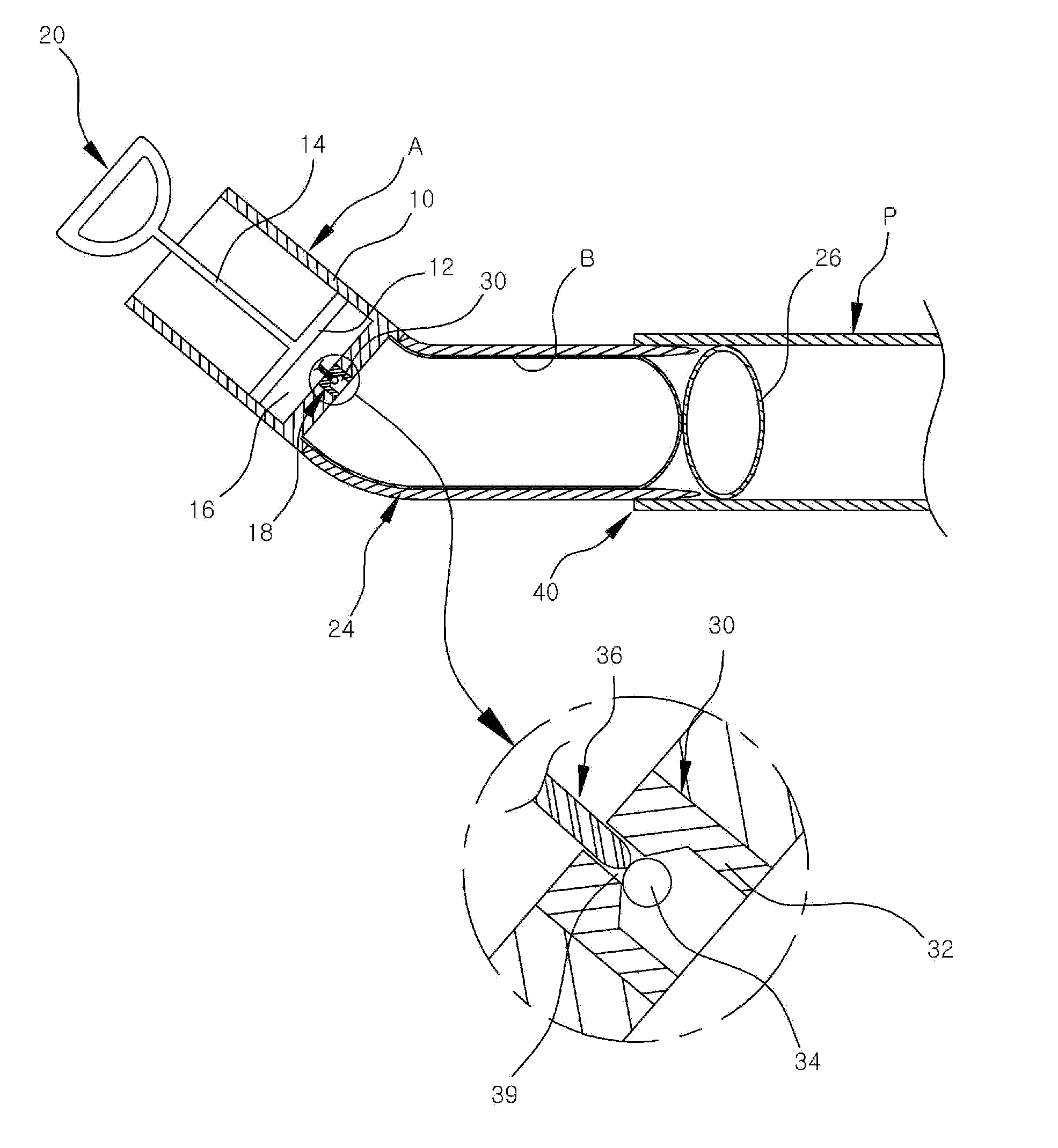
[0020]Reference will be now made in detail to the preferred embodiments of the present invention with reference to the attached drawings. First, a first preferred embodiment of the present invention illustrated in FIG. 1 will be described. The device for clearing the pipe blockage according to the present invention uses a flexible inflatable balloon (B). The inflatable balloon (B) expands by injection of air and is returned to its original size when air is removed.

[0021]When the expanding inflatable balloon (B) is inserted into the inside of a pipe (P), high pressure may be formed between the inside of the pipe (P) and a blocked part, or shock pressure may be generated by a back-and-forth movement of the inflatable balloon (B) inserted into the pipe. It is obvious that the shock pressure formed by the movement of the inflatable balloon inside the pipe or the high pressure formed by expansion of the inflatable balloon can be a spur to clear the blocked part of the pipe (P).

[0022]The ...


PUM


Abstract

A device for clearing pipe blockage includes: pumping means (A) for compressing air by pumping and having an outlet (18) for discharging compressed air out; and an inflatable balloon mounted at the outlet and expanding by air discharged through the outlet. The outlet is a one-way valve, and a cylindrical guide member (24) is formed to surround the outside of the inflatable balloon, guides the inflatable balloon to move forward inside a pipe when a front end part of the guide member is inserted into the pipe, and is made of flexible material. A presser which cleans the inner surface of the pipe while moving in a state where it gets in contact with the inner surface of the pipe is mounted at a front end of the inflatable balloon, and the blocked pipe is cleared by shock pressure by movement of the pumping unit and a change in pressure by expansion of the inflatable balloon by the compressed air.

Description

REFERENCE TO RELATED APPLICATIONS[0001]This application claims the priority benefit of Korean Patent Application No. 10-2014-0034903 filed on Mar. 25, 2014, and Korean Patent Application No. 10-2015-0018006 filed on Feb. 5, 2015, the entire contents of which are incorporated herein by referenceFIELD OF THE INVENTION[0002]The present invention relates to a device for clearing blockage of a pipe which drains water of a toilet or a sin, and more particularly, to a device for clearing blockage of a pipe which can clear the inside of a blocked pipe using a balloon expanding by injection of air.BACKGROUND OF THE INVENTION[0003]In general, toilets, washstands and sinks are designed to discharge foreign matters out when water is drained. Moreover, because a part to drain water adopts a U-shaped trap structure in order to prevent a bad smell from backing up, such a trap structure causes pipe blockage. In addition to such a structural reason, of course, pipes of the toilets, washstands and si...

Claims


Application Information

Patent Timeline
IPC IPC(8): B08B9/055
CPCB08B9/055E03C1/308B08B9/0557
Inventor KIM, YONG SOO
Owner KIM YONG SOO
Learn More