Module for an aircraft

a technology for modules and aircrafts, applied in the field of modules for aircrafts, can solve the problems of poor access to belongings, inefficient turnaround time, and passengers' interference, and achieve the effect of stable installation of functional elements

Inactive Publication Date: 2015-09-17
AIRBUS SAS +1
View PDF23 Cites 4 Cited by
  • Summary
  • Abstract
  • Description
  • Claims
  • Application Information

AI Technical Summary

Benefits of technology

This patent aims to provide a lighter and more flexible connection system for functional elements in structures such as vehicles. The invention uses a plurality of frame devices that can be easily replaced without connecting them, providing more flexibility. The connections between the frame devices are designed to withstand loads of 16 g in each direction, and the forces affecting functional elements are reduced by connecting them in multiple planes. This results in a lighter and more efficient connection system that meets current safety standards.

Problems solved by technology

The opening of the stowage bins is typically above the aisle orthogonal to the longitudinal direction of the fuselage, so that the passengers interfere themselves.
This results in inefficient turnaround time and the poor access to the belongings during the flight.

Method used


Image

  • Module for an aircraft
  • Module for an aircraft
  • Module for an aircraft

Examples


Embodiment Construction

[0070]Similar or relating components in the several figures are provided with the same reference numerals. The view in the figures is schematic and not fully scaled.

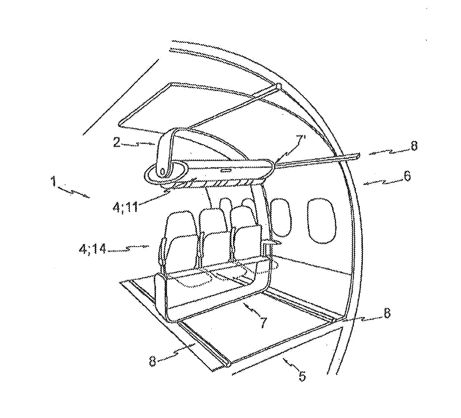
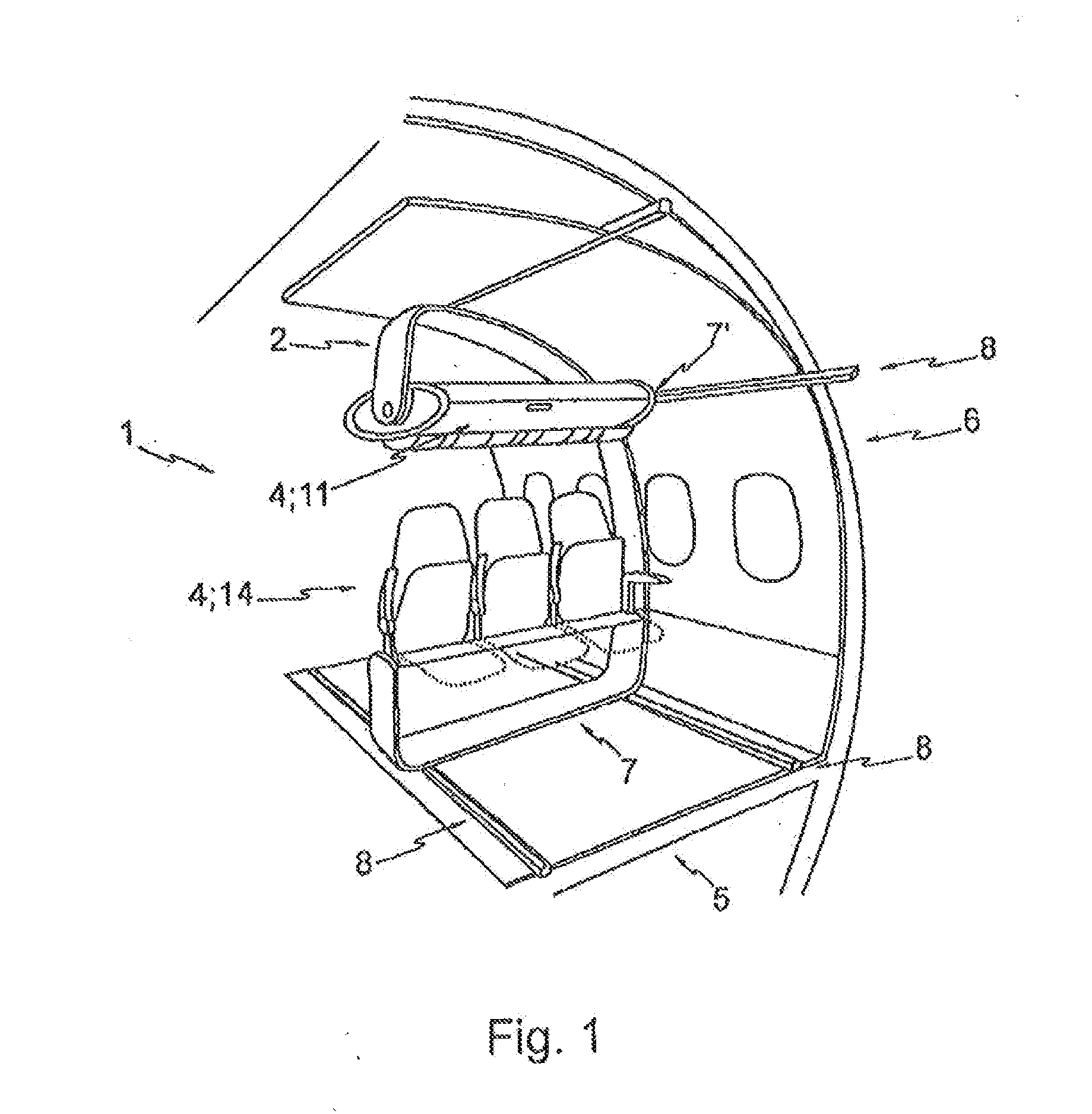
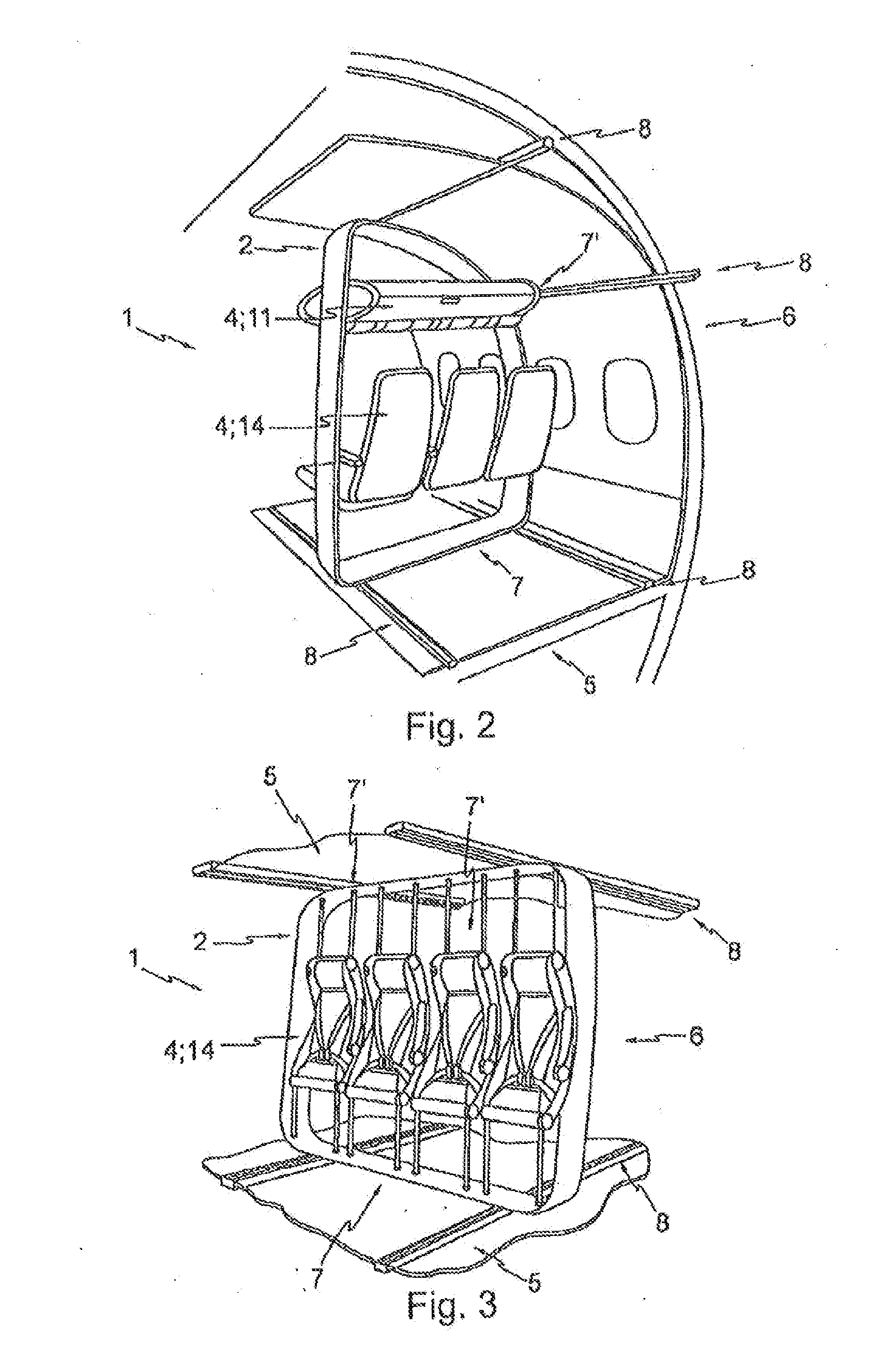
[0071]FIGS. 1 to 3 illustrate schematic views of exemplary embodiments of the present invention. A module for an aircraft is shown, wherein the aircraft having a fuselage structure 6 and a floor element 5. The floor element 5 defining a floor plane. The module comprises a frame device 2 wherein the frame device 2 is adapted for mounting a functional element 4. The frame device 2 is adapted for attachment to the floor element 5 of the aircraft at a first location 7 in the floor plane and wherein the frame device 2 is adapted for attachment to the fuselage structure 6 of the aircraft at a second location 7′. The second location 7′ is thereby not in the floor plane.

[0072]It is further illustrated a rail element 8 whereby the frame device 2 can be fixed relocatable respectively movable to the rail 8. By using as shown an air...


PUM


Abstract

A module for an aircraft has a fuselage structure and a floor element defining a floor plane. The module includes a frame device adapted for mounting a functional element and the frame device is adapted for attachment to the floor element of the aircraft at a first location in the floor plane.

Description

CROSS-REFERENCE TO RELATED APPLICATIONS[0001]The present application is a continuation of U.S. patent application Ser. No. 12 / 087,328, filed on May 28, 2009, which application is a national phase entry under 35 U.S.C. §371 of International Application No. PCT / EP2006 / 012545 filed Dec. 27, 2006, which claims priority from European Patent Application No. 05 028 664.0 filed Dec. 29, 2005, which claims priority from U.S. Provisional Patent Application No. 60 / 754,745 filed Dec. 29, 2005, all of which are hereby incorporated herein by reference.TECHNICAL FIELD[0002]The present invention relates to a module, a system and a method for aircrafts, the use of a module in an aircraft and to an aircraft.BACKGROUND OF THE INVENTION[0003]Today's commercial aircraft cabins are designed to accommodate passengers and their luggage by providing several distinct and largely independent components. More precisely, the individual passenger cabin environment is made up of seats, for instance including unde...

Claims


Application Information

Patent Timeline
Patent Type & Authority Applications(United States)
IPC IPC(8): B64D11/00B64D11/06B64C1/18
CPCB64D11/003B64D11/06B64C1/18B64D11/00B64D11/0601B64D11/0604B64D11/0611B64D11/06395B64D11/0696B64D2011/0046Y02T50/40Y10T29/49826B64D11/0015B64D11/00154B64D11/0626B64D11/0627B64D11/0631B64D11/0639B64D11/0649B64D2011/0053
Inventor SAINT-JALMES, BRUNOREZAG, ANDREZANEBONI, JASONSCHUMACHER, MARKUSMUIN, ANDREWHAACK, CORDCARR, MICHAEL
Owner AIRBUS SAS
Why Eureka
Try Eureka