
Supporting counter-frame for sliding doors of fridge cabinets

a technology for fridge cabinets and counter-frames, which is applied in the direction of building components, applications, lighting and heating apparatus, etc., can solve the problems of recurring defects of conventional automatic closing systems for sliding doors, inability to adjust the restoring force of the closing mechanism, and inability to close too quickly, etc., to achieve easy and precise assembly, easy and precise, and the effect of mounting in a very short tim

Inactive Publication Date: 2015-09-10
CIANETTI
View PDF11 Cites 19 Cited by
  • Summary
  • Abstract
  • Description
  • Claims
  • Application Information

AI Technical Summary

Benefits of technology

The patent text describes a design feature for sliding doors of a fridge cabinet. The design includes a locking lever that is attached to the upper bracket of a sliding door and can be rotated for easy loading and unloading of goods. The sliding doors also have anti-friction slides to prevent friction that may occur when the doors are misaligned. The technical effect of this design is improved efficiency and ease of operation for opening and closing the sliding doors of a fridge cabinet.

Problems solved by technology

Nonetheless, conventional automatic closing systems for sliding doors present some recurring defects:
the restoring force of the closing mechanism can be maladjusted; the force of the closing mechanism is not sufficient to pull the sliding door back into the full closed position or the force is so over-dimensioned that the closing is too quick, which might be dangerous for customers and, finally, might damage the fridge cabinet;
The building systems of conventional counter-frames and frames for sliding doors also present some defects:
sometimes they are so complex that it is difficult to remove the sliding door from the counter-frame, which makes it difficult to clean the area between the counter-frame and the frames of the doors; this area must be cleaned regularly, both for health reasons and to ensure that the fridge cabinet looks clean to the customers;
the section bars forming the traditional counter-frame and frame are bulky and hinder the optimal view of the displayed goods.

Method used


Image

  • Supporting counter-frame for sliding doors of fridge cabinets
  • Supporting counter-frame for sliding doors of fridge cabinets
  • Supporting counter-frame for sliding doors of fridge cabinets

Examples


Embodiment Construction

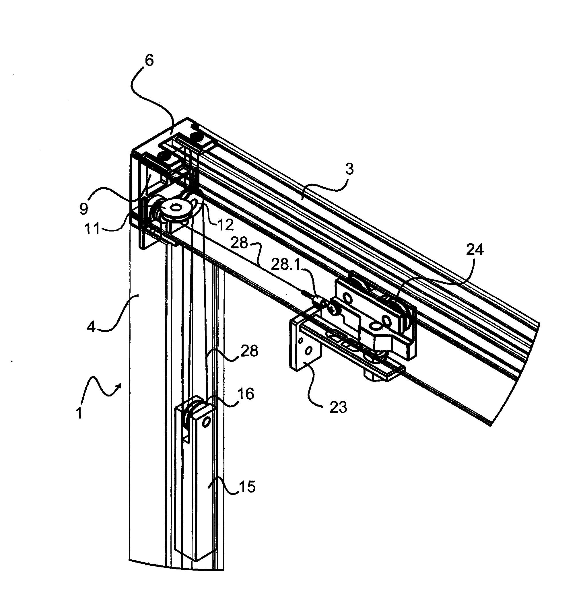
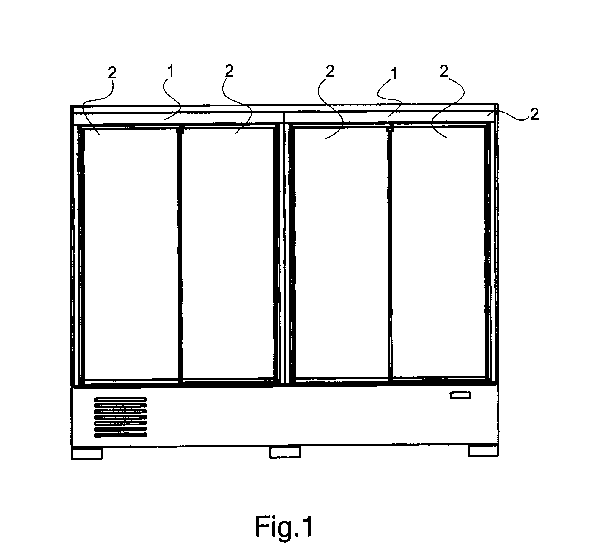
[0065]As shown in FIGS. 1-18, two supporting counter-frames 1 according to the invention are installed on a fridge cabinet. The two supporting counter-frames 1 delimit peripherally the access opening to the refrigerated space of the fridge cabinet. Each supporting counter-frame 1 supports two sliding doors 2 closing the display space. The sliding doors 2 of each counter-frame 1 are parallel to each other.

[0066]Each supporting counter-frame 1 is composed of a metal supporting upper section bar 3 constituting the upper transom, of two plastic vertical section bars 4 constituting the upright s and of a lower section bar 5 constituting the lower transom. Each section bar 3, 4, 5 of the counter-frame 1 has first guides 3.1, 4.1, 5.1, parallel to its longitudinal axis, along the surface facing the edges of the access opening to the refrigerated space.

[0067]Inside the upper section bar 3 there are two arms 3.2, one end of which is enlarged, dividing the inner space of the upper section bar...


PUM


Abstract

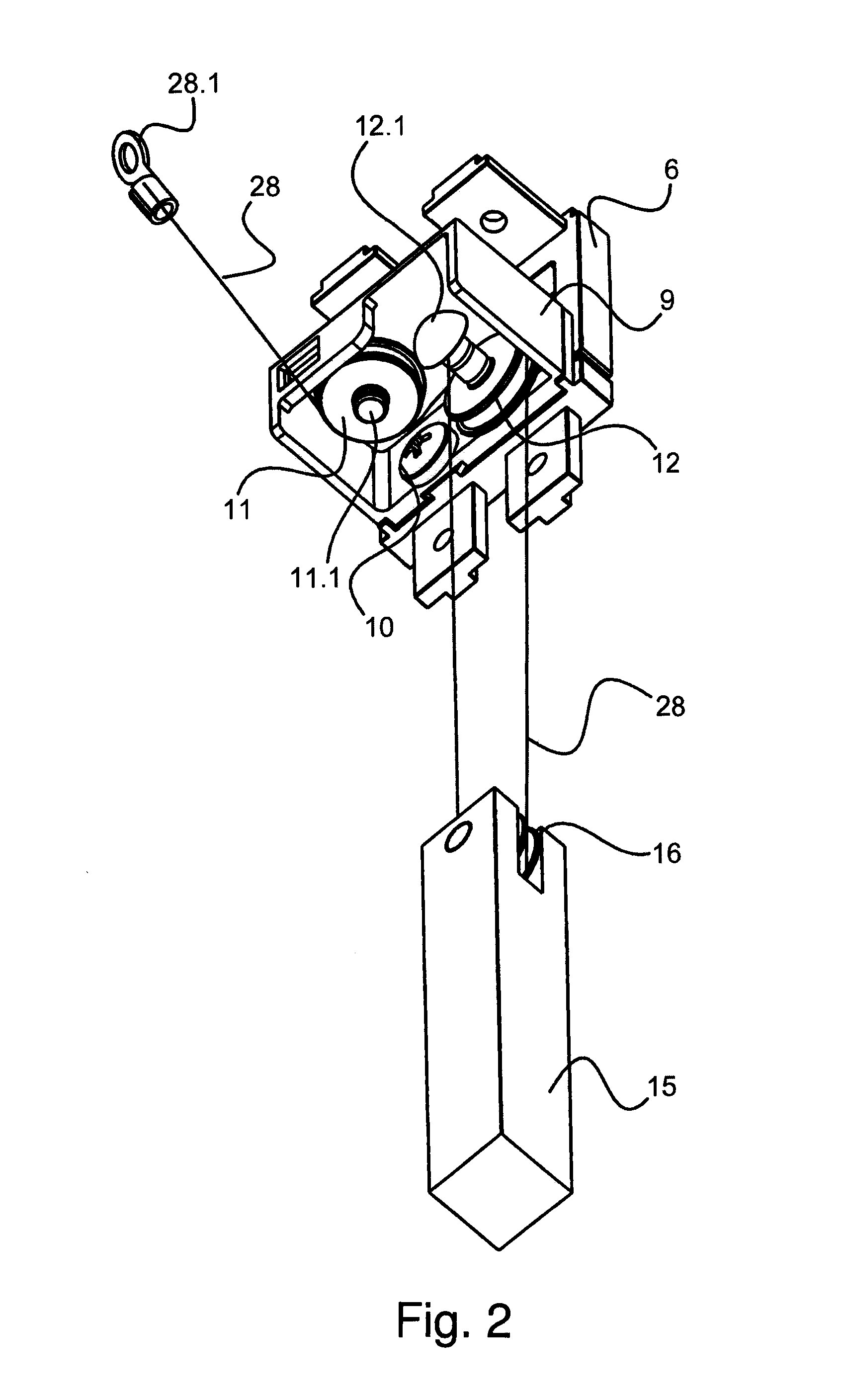
A supporting counter-frame for sliding doors with an automatic closing system comprising, for each sliding door (2), a first pulley (11), a second pulley (12), a counterweight (15) equipped with a third pulley (16) and a motion transmission cable (28); said counterweight (15) is housed within a vertical section bar (4) of the counter-frame (1); one end of the cable (28) is fixed to a trolley (24) of a sliding door (2) and slides till the first pulley (11) along the sliding direction of the sliding door (2), from the first pulley (11) to the second pulley (12) horizontally and orthogonally to the sliding movement of the sliding door (2) and finally from the second pulley (12) to the third pulley (16) of the counterweight (15) and again to the second pulley (12) vertically and orthogonally to the sliding movement of the sliding door (2).

Description

FIELD OF THE INVENTION[0001]This invention refers to a supporting counter-frame for sliding doors of fridge cabinets comprising an automatic closing system, specifically the fridge cabinets used in sales outlets to display and sell packaged food, drinks and other foodstuffs which shall be kept at a controlled negative or positive temperature.STATE OF THE ART[0002]The sliding doors of the fridge cabinets intended for the sale of foodstuffs shall always remain closed to save frigories and to constantly control the inner temperature of the cabinet in order to prevent the food from warming up and from thus losing its flavour or even deteriorating.[0003]The sliding doors are supported by a peripheral supporting counter-frame delimiting the access opening to the refrigerated space.[0004]Each sliding door is composed of a frame encircling a transparent glass or plastic plate or an insulating blind plate. The doors slide freely while resting on lower guides of the lower section bar of the c...

Claims


Application Information

Patent Timeline
IPC IPC(8): E05D13/00F25D23/02E06B3/46E06B5/00E05D15/06E05F1/02
CPCE05D13/10E05D15/0652E05D15/063E05F1/025E05F2017/005E06B5/00F25D23/021F25D23/028E06B3/4645E05Y2900/204E05D13/14E05D15/08E05Y2900/31
Inventor CIANETTI, ALESSANDRO
Owner CIANETTI
Learn More