Liquid-crystal display device and drive method thereof

a display device and liquid crystal technology, applied in the direction of electric digital data processing, instruments, computing, etc., can solve the problem that the liquid crystal display device mounted in such electronic equipment has been required to consume low electric power, and achieve the effect of reducing the number of refreshes, reducing the refresh rate, and changing more quickly

Active Publication Date: 2015-09-03
SHARP KK
View PDF3 Cites 16 Cited by
  • Summary
  • Abstract
  • Description
  • Claims
  • Application Information

AI Technical Summary

Benefits of technology

[0037]According to the first aspect of the present invention, the refresh rate in the second refresh period is changed more quickly than the refresh rate in the first refresh period. Hence it is possible to finish in a short time the first refresh period for performing a refresh required for making an afterimage, which is visually recognized at pause drive time, visually unrecognizable, and reach the target refresh rate for the pause drive more quickly while lowering the refresh rate in stages. As a result, it is possible to promptly make an afterimage visually unrecognizable after the first refresh is performed in the first frame. Further, it is possible to make a shift to the target refresh rate for the pause drive in a short time, so as to reduce the number of times of refreshes during and after the shift to the target refresh rate. Hence it is possible to reduce the power consumption of the liquid crystal display device in this period.
[0038]According to the second aspect of the present invention, since the amount of change in number of non-refresh frames in the second refresh period is larger than the amount of change in number of non-refresh frames in the first refresh period, it is possible to make a shift to the target refresh rate for the pause drive in a short time.
[0039]According to the third aspect of the present invention, by performing a plurality of times of refreshes in the second refresh period, it is possible to reach the target refresh rate for the pause drive in a short time while suppressing deterioration in display quality of the image. Hence it is possible to reduce the power consumption of the liquid crystal display device from the start of the pause drive until the reach to the target refresh rate.
[0040]According to the fourth aspect of the present invention, it is possible to increase the number of frames in every non-refresh period in the second refresh period in arithmetic progression with a common difference of not smaller than 2, so as to reach the target refresh rate more quickly while lowering the refresh rate in stages. Hence it is possible to reduce the power consumption of the liquid crystal display device from the start of the pause drive until the reach to the target refresh rate.
[0041]According to the fifth aspect of the present invention, it is possible to increase the number of frames in every non-refresh period in the second refresh period in geometric progression with a common ratio of not smaller than 2, so as to reach the target refresh rate further more quickly while lowering the refresh rate in stages. Hence it is possible to further reduce the power consumption of the liquid crystal display device from the start of the pause drive until the reach to the target refresh rate.
[0042]According to the sixth aspect of the present invention, in the second refresh period, the refresh rate is not changed in stages, but is lowered straight to the target refresh rate for the pause drive. Thereby it is possible to reach the target refresh rate in the shortest time, and reduce the number of times of refreshes during and after the shift to the target refresh rate. Hence it is possible to significantly reduce the power consumption of the liquid crystal display device in this period.

Problems solved by technology

A liquid crystal display device mounted in such electronic equipment has been required to consume low electric power.

Method used


Image

  • Liquid-crystal display device and drive method thereof
  • Liquid-crystal display device and drive method thereof
  • Liquid-crystal display device and drive method thereof

Examples


first embodiment

2. First Embodiment

2.1 Configuration and Operation Summary of Liquid Crystal Display Device

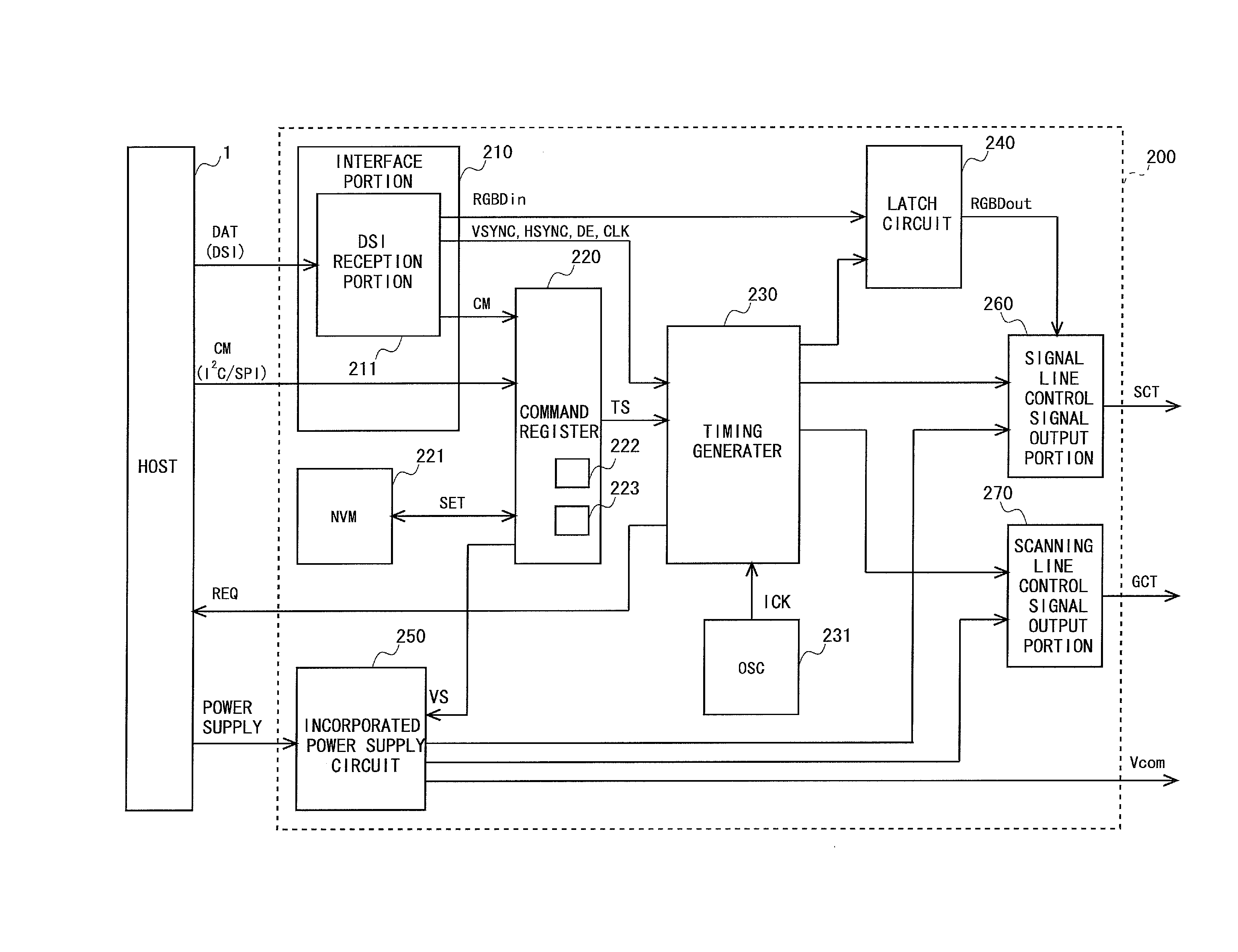
[0086]FIG. 4 is a block diagram showing a configuration of a liquid crystal display device 2 according to a first embodiment of the present invention. As shown in FIG. 4, the liquid crystal display device 2 is provided with a liquid crystal display panel 10 and a backlight unit 30. The liquid crystal display panel 10 is provided with an FPC (Flexible Printed Circuit) 20 for connection with the outside. Further, a display portion 100, a display control circuit 200, a signal line drive circuit 300 and a scanning line drive circuit 400 are provided on the liquid crystal display panel 10. It is to be noted that both or either one of the signal line drive circuit 300 and the scanning line drive circuit 400 may be provided in the display control circuit 200. Further, both or either one of the signal line drive circuit 300 and the scanning line drive circuit 400 may be formed integrally with the disp...

second embodiment

3. Second Embodiment

[0129]FIG. 11 is a diagram for explaining an operation of the liquid crystal display device 2 according to a second embodiment of the present invention. It is to be noted that, since the present embodiment is similar to the above first embodiment except for the operation, there will be omitted a block diagram showing the configuration of the liquid crystal display device 2 and the configuration of the display control circuit 200 included in the liquid crystal display device 2, and descriptions thereof.

3.1 Operation

[0130]In the above first embodiment, the first refresh period for making an afterimage visually unrecognizable at the refresh time and the second refresh period for changing the display luminance in stages have been provided. In the present embodiment, as shown in FIG. 11, the first refresh period is the same as in the case of the first embodiment, but the second refresh period is very short.

[0131]Specifically, in the first refresh period, first, the f...

third embodiment

4. Third Embodiment

[0134]FIG. 12 is a diagram for explaining an operation of the liquid crystal display device 2 according to a third embodiment of the present invention. It is to be noted that, since the present embodiment is similar to the above first embodiment except for the operation, there will be omitted a block diagram showing the configuration of the liquid crystal display device 2 and the configuration of the display control circuit 200 included in the liquid crystal display device 2, and descriptions thereof.

4.1 Operation

[0135]Throughout the first and second refresh periods, when a balance between positive polarity and negative polarity of the applied voltage of the liquid crystal capacitance Ccl is not considered, the time when a voltage in a specific direction is applied to the liquid crystal layer becomes long, causing the deterioration in liquid crystal layer to tend to gets worse. Accordingly, in the present embodiment, the deterioration in liquid crystal layer is s...


PUM


Abstract

Provided are a liquid crystal display device and a drive method thereof, capable of promptly making an afterimage, which is visually recognized at refresh time, visually unrecognizable and reducing power consumption during and after a shift to a target refresh rate. At pause drive time until a target refresh rate is reached, a refresh is performed in divided periods of a first refresh period for performing a refresh at least twice, and a second refresh period for performing a refresh while increasing the number of frames in a non-refresh period from a refresh rate at the end of the first refresh period until the refresh rate becomes the target refresh rate, and the second refresh period is finished when the refresh rate in the second refresh period reaches the target refresh rate, and the pause drive is continued at the target refresh rate.

Description

TECHNICAL FIELD[0001]The present invention relates to a liquid crystal display device and a drive method thereof, and specifically relates to a liquid crystal display device that displays an image by pause drive, and a drive method thereof.BACKGROUND ART[0002]In recent years, small-sized lightweight electronic equipment has been under active development. A liquid crystal display device mounted in such electronic equipment has been required to consume low electric power. As one of drive methods for reducing power consumption of the liquid crystal display device, there is a drive method called “pause drive” provided with a drive period for scanning scanning lines to write a signal voltage and a pause period for bringing all scanning lines into a non-scanning state to make writing pause. In the pause drive, in the pause period, a controlling signal or the like is prevented from being given to a scanning line drive circuit and / or a data signal line drive circuit, to make pause operation...

Claims


Application Information

Patent Timeline
Patent Type & Authority Applications(United States)
IPC IPC(8): G09G5/18G09G3/36
CPCG09G3/3618G09G5/18G09G3/3648G09G2340/0435
Inventor TANAKA, NORIYUKISONE, TAKUYA
Owner SHARP KK
Why Eureka
Try Eureka