Test Handler and Circulation Method of Test Trays in Test Handler
- Summary
- Abstract
- Description
- Claims
- Application Information
AI Technical Summary
Benefits of technology
Problems solved by technology
Method used
Image

Examples
first embodiment
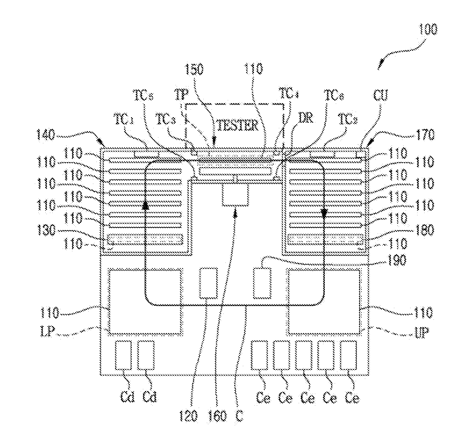
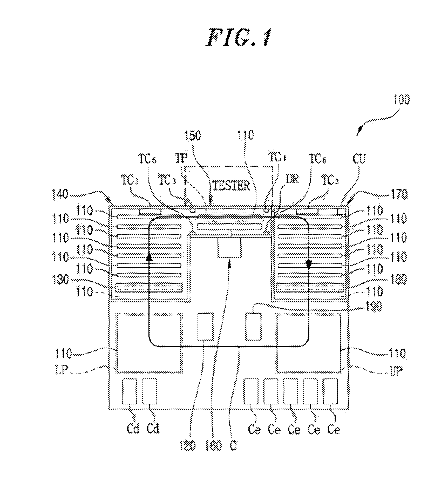
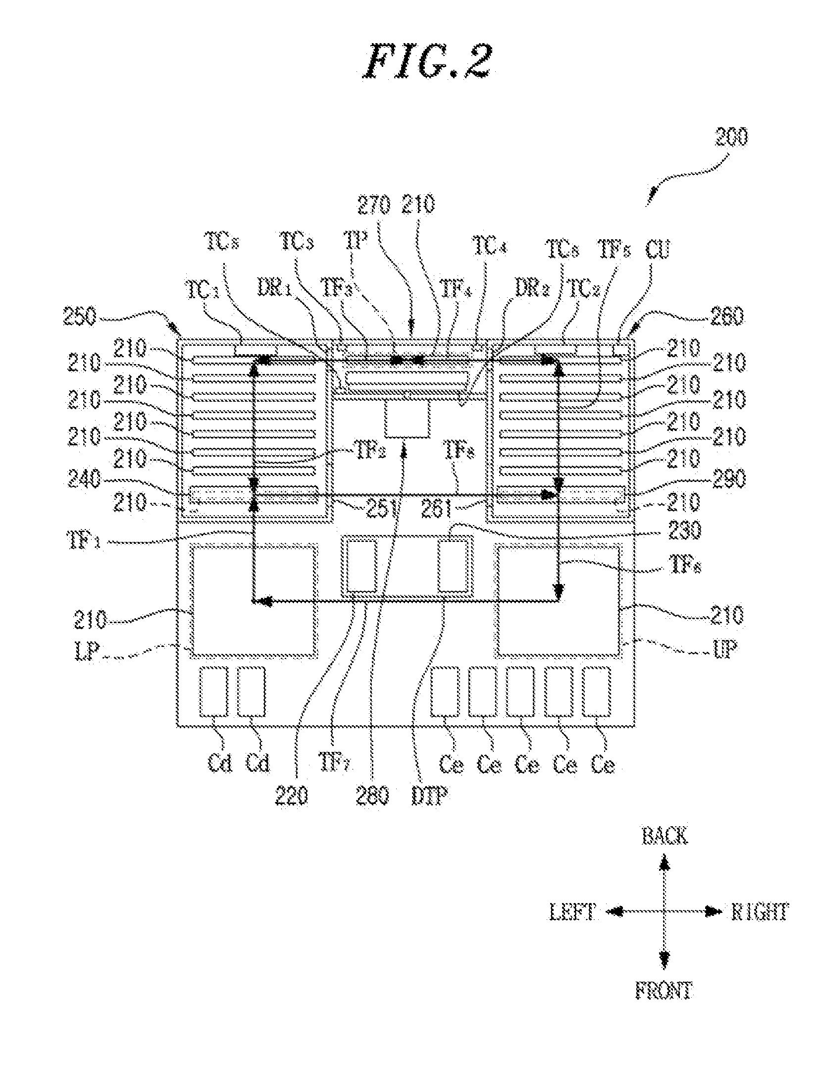
[0048]FIG. 2 is a conceptual plan view of a test handler 200 in accordance with the present invention.
[0049]As shown in FIG. 2, the test handler 200 includes a test tray 210, a loading unit 220, an unloading unit 230, a first position converter 240, a first chamber 250, a second chamber 260, a test chamber 270, a pressure device 280, a second position converter 290, a plurality of transporters (TF1 to TF8), a plurality of thermo-regulators (TC1 to TC6) and a controller (CU).
[0050]The test tray 210 circulates along a first circulation path (C1 in FIG. 3) or a second circulation path (C2 in FIG. 4), depending on the temperature condition of test. Here, the first circulation path (C1) is a closed path leading from a loading position (LP), an inside of the first chamber 250, a test position (TP) in the inside of the test chamber 270, an inside of the second chamber 260 and an unloading position (UP) to the loading position (LP). The second circulation path (C2) is a path which is used w...
second embodiment
[0082]FIG. 10 and FIG. 11 show a first circulation path (C1) and a second circulation path (C2) of a test tray 310 of a test handler 300 in accordance with a second embodiment of the present invention.
[0083]In the test handler 300 in accordance with the present embodiment, loading and unloading are made at the same location, as Korean Patent Laid-Open Publication No. 10-1998-056230 or Korean Registered Patent No. 10-0560729.
[0084]In this case, as referenced in FIG. 10, the first circulation path (C1) is a closed path leading from a loading / unloading position (L / UP), an inside of a first chamber 350, a test position of an inside of a test chamber 370 and an inside of a second chamber 360 sequentially to the loading / unloading position (L / UP). As referenced in FIG. 11, the second circulation path (C2) is a closed path leading from the loading / unloading position (L / UP), the inside of the second chamber 360, the test position of the inside of the test chamber 370 and the inside of the fi...
third embodiment
[0085]FIG. 12 and FIG. 13 show a first circulation path (C1) and a second circulation path (C2) of a test handler 400 in accordance with a third embodiment of the present invention.
[0086]The test handler 400 in accordance with the present embodiment is an under-head docking type, and there is no conversion of position of a test tray 410.
[0087]In the present embodiment, as referenced in FIG. 12, the first circulation path (C1) is a close path leading from a loading position (LP), an inside of a first chamber 450, 410 is transferred in parallel from the inside of the first chamber 450 to the downward>, a test position (TP) of an inside of a test chamber 470, an inside of a second chamber 460, 410 is transferred in parallel from the inside of the second chamber 460 to the upward>, and an unloading position (UP) sequentially to the loading position (LP). As referenced in FIG. 13, the second circulation path (C2) is a close path leading from the loading position (LP), the inside of a fir...
PUM
 Abstract
Description
Claims
Application Information
 - R&D
- Intellectual Property
- Life Sciences
- Materials
- Tech Scout
- Unparalleled Data Quality
- Higher Quality Content
- 60% Fewer Hallucinations
Browse by: Latest US Patents, China's latest patents, Technical Efficacy Thesaurus, Application Domain, Technology Topic, Popular Technical Reports.
© 2025 PatSnap. All rights reserved.Legal|Privacy policy|Modern Slavery Act Transparency Statement|Sitemap|About US| Contact US: help@patsnap.com