
Remotely operated target-processing system

a target processing and remote operation technology, applied in the direction of weapons, launching weapons, armoured vehicles, etc., can solve the problems of complex aiming and shooting systems, achieve the effects of less complex realisation, reduced acquisition and maintenance costs, and simple and flexible implementation

Active Publication Date: 2015-09-03
LEVILLY PHILIPPE
View PDF15 Cites 7 Cited by
  • Summary
  • Abstract
  • Description
  • Claims
  • Application Information

AI Technical Summary

Benefits of technology

The present invention aims to develop a target-processing system that is easy to use, flexible to implement, and effective in reducing the number of shots required to neutralize a target. The system should also provide a precise prediction of the impact point of the projectiles, increasing the likelihood of hitting the target. This will result in reduced costs of acquisition and maintenance.

Problems solved by technology

These aiming and shooting systems are very complex for the most part and the outcome from them when these systems are implemented is often more to do with the number of missiles fired than with the precision with which the target is located.

Method used


Image

  • Remotely operated target-processing system
  • Remotely operated target-processing system
  • Remotely operated target-processing system

Examples


Embodiment Construction

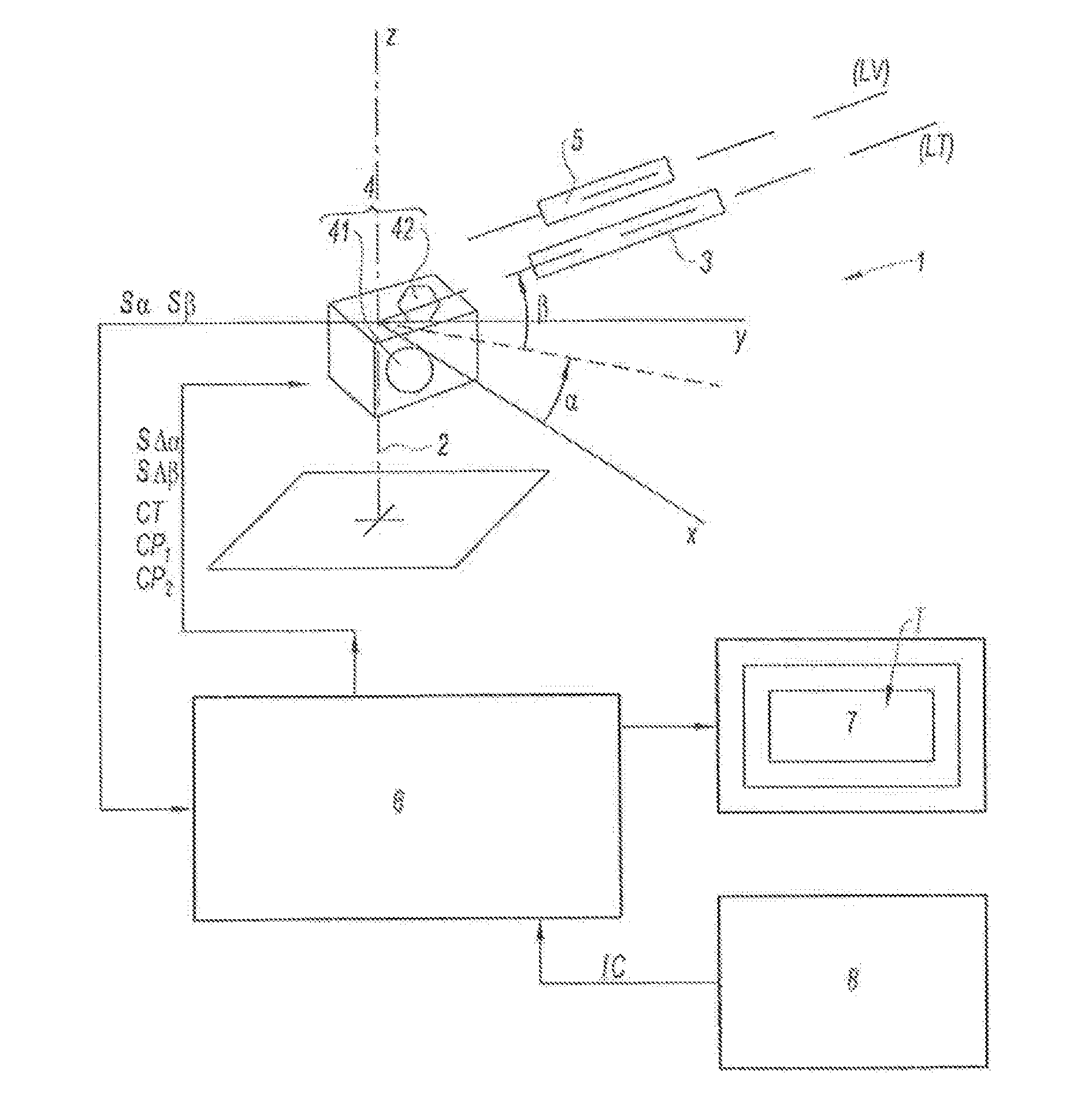
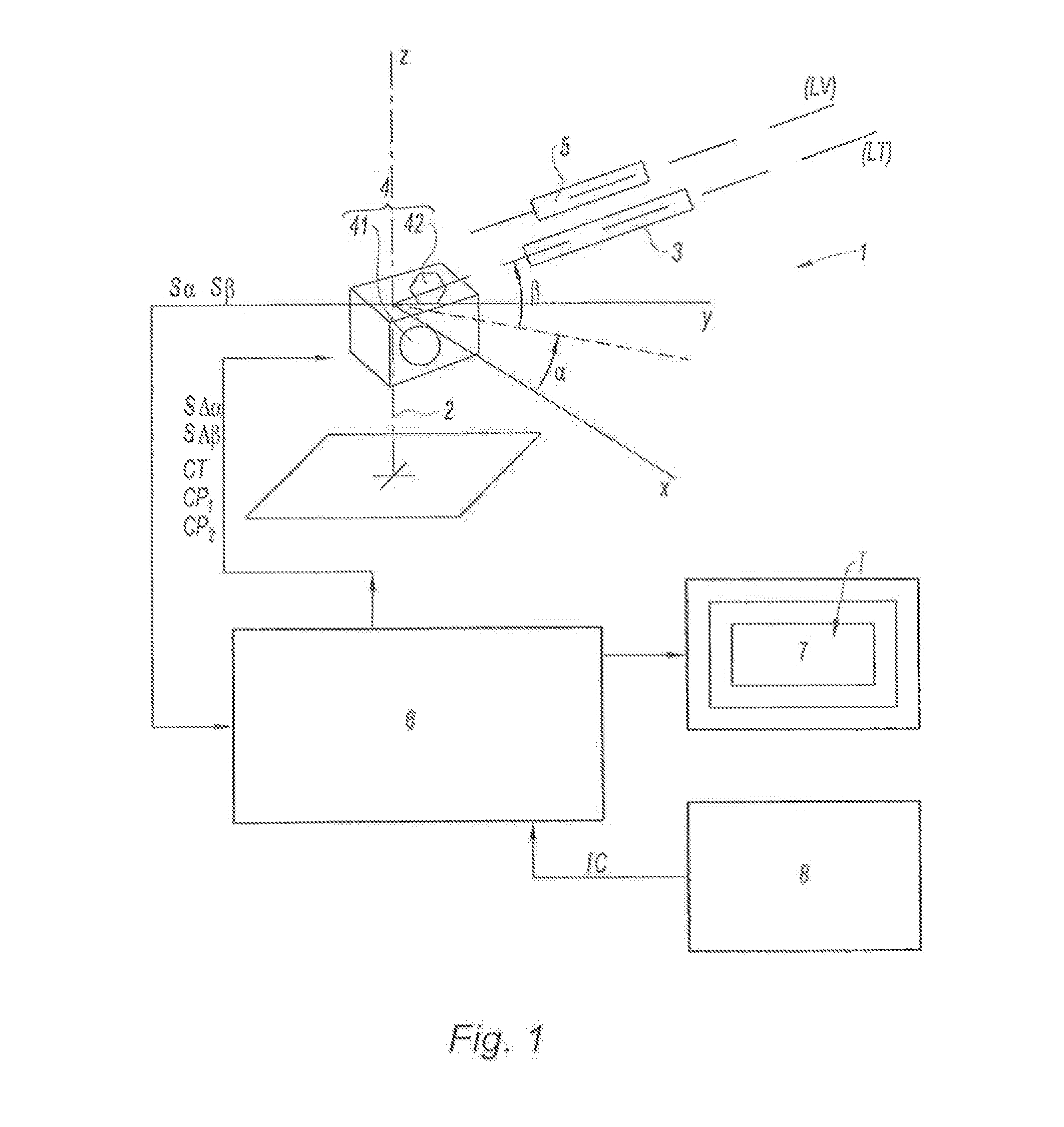
[0057]According to FIG. 1, the aim of the invention is a remotely operated target-processing system and, to achieve this, it comprises, as shown in a very diagrammatic manner, a shooting robot 1 having a stand in the form of a foot 2, installed so that it is fixed or deployed on a vehicle and carrying a firing part 3 by means of a set 4 of positioning actuators 41, and sensors 42, very simplified, that detect the relative position of the firing part 3. The firing part 3 is linked to an optoelectronic aiming device 5 providing an image (I) of the target (not shown in this illustration).

[0058]FIG. 1 shows a reference drawn on the stand 2, for example an orthonormal set (xyz) whose origin is O, situated on the trajectory line LT of the firing part 3 and which enables the bearing (α) and the position (β) of the trajectory line to be defined.

[0059]The optoelectronic device 5 linked to the firing part 3 has a line of sight LV. The trajectory line LT and the line of sight LV are practicall...


PUM


Abstract

A remotely operated target-processing system includes a shooting robot having a stand supporting a firing part having an optoelectronic aiming device providing an image of the target, sensors detecting the relative position of the firing part, and actuators positioning the firing-part. A central unit receives the instructions and the signals from the sensors and generates control signals for the actuators and the firing-part. A control screen displays the image and embeds aiming data, and a control member directs the trajectory line.

Description

CROSS-REFERENCE TO RELATED APPLICATIONS[0001]This application is a U.S. National Phase Patent Application based on International Application No. PCT / FR2013 / 050668 filed Mar. 28, 2013, which claims priority to French Patent Application No. 1253382 filed Apr. 12, 2012, the entire disclosures of which are hereby explicitly incorporated by reference herein.BACKGROUND OF THE INVENTION[0002]1. Field of the Invention[0003]The invention relates to a remotely operated target-processing system.[0004]2. Description of the Related Art[0005]In general, a number of systems exist that track targets and neutralise them. These aiming and shooting systems are very complex for the most part and the outcome from them when these systems are implemented is often more to do with the number of missiles fired than with the precision with which the target is located.[0006]These systems usually depend on locating the geographical position of the target, the co-ordinates of which are fed into a tracking system...

Claims


Application Information

Patent Timeline
Patent Type & Authority Applications(United States)
IPC IPC(8): F41G5/06F41G3/16F41G3/32F41G3/14
CPCF41G5/06F41G3/323F41G3/165F41G3/142F41G5/26F41H7/005
Inventor LEVILLY, PHILIPPE
Owner LEVILLY PHILIPPE
Learn More