
Motor vehicle headlamp

a headlamp and motor vehicle technology, applied in the field of headlamps, can solve the problems of small variance, additional loss of luminous flux in the beam path, and the structural length of the light module, and achieve the effect of significantly reducing the structural length of the lens

Active Publication Date: 2015-08-27
AUTOMOTIVE LIGHTING REUTLINGEN GMBH
View PDF2 Cites 37 Cited by
  • Summary
  • Abstract
  • Description
  • Claims
  • Application Information

AI Technical Summary

Benefits of technology

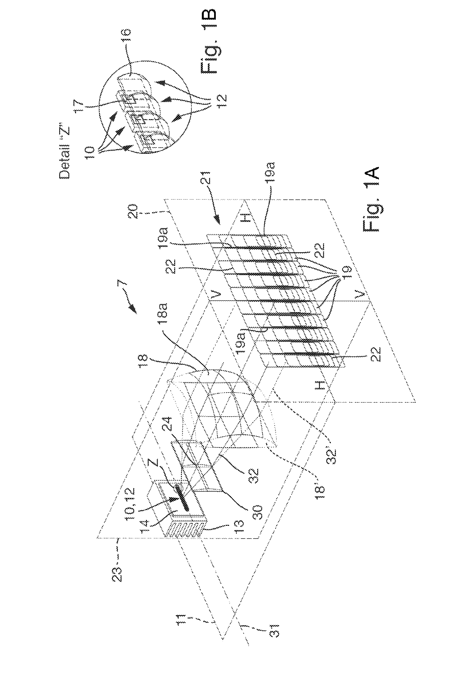
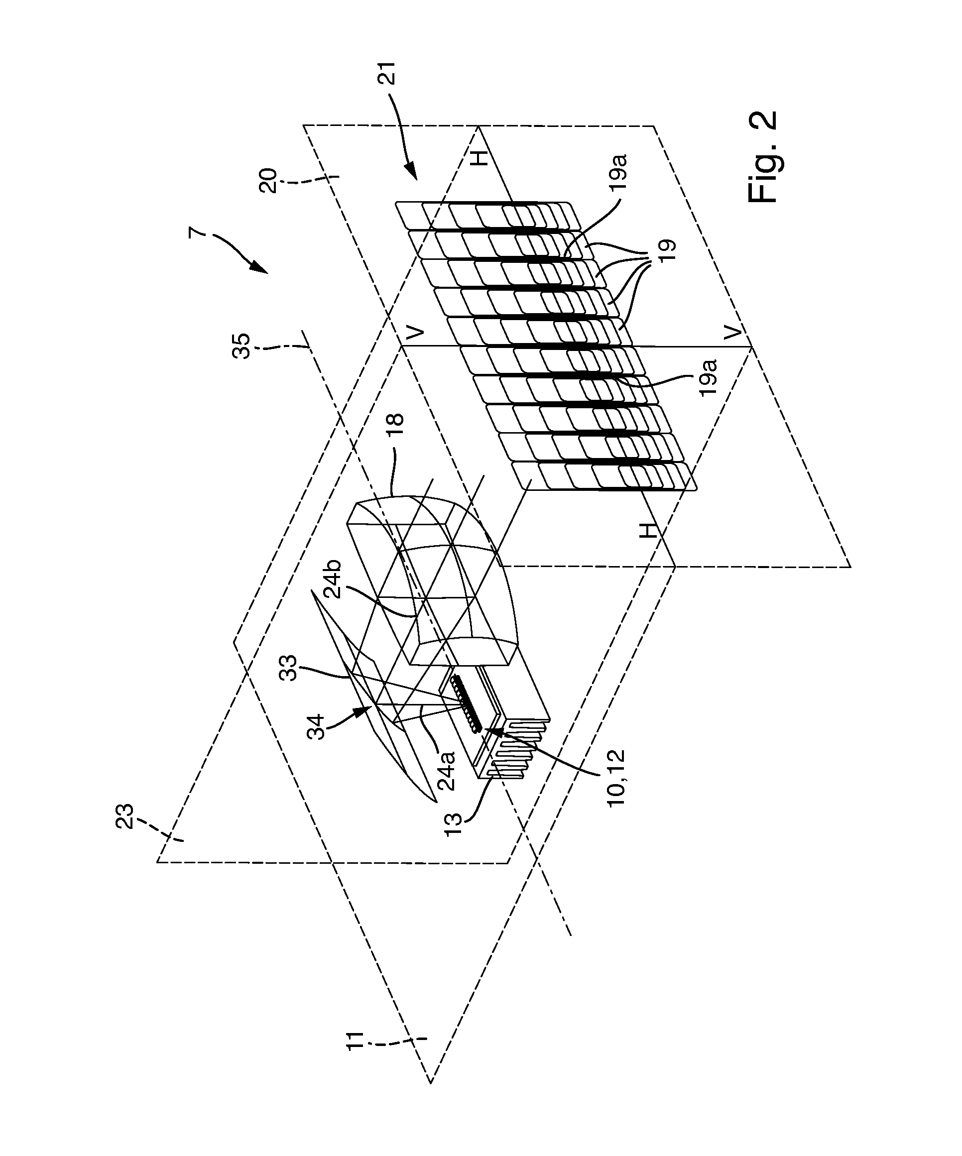
The present invention overcomes the disadvantages in creating a light module for generating at least two stripe-shaped secondary light distributions, immediately adjacent to one another in at least one line, or overlapping, with which the at least two adjacent secondary light distributions are formed by numerous semiconductor light sources or light source groups, and with which the structural height of the secondary lens can be reduced without substantial losses in luminous flux. The invention has the advantages of a shorter structural length with respect to known light modules, while still exhibiting comparable performance characteristics (e.g. resolution, maximum luminosity, etc. The cylindrical lens can significantly reduce the aperture angle of the light bundle from the primary lenses in the vertical cross-section, such that secondary light distributions (so-called pixels) are obtained, the heights of which can be a multiple of the respective pixel widths. This is caused by, among other things, the increasingly aerodynamic shapes of the fronts of vehicles, for achieving greater fuel efficiency andlower airflow noises. A cylindrical concave mirror can also bend the beam path and significantly reduce the structural length of the lens.

Problems solved by technology

The large gradient in the illumination can be subjectively experienced by a driver of the motor vehicle as having a disruptive effect.
With lens systems, the aberrations are primarily color errors, whereas with reflection systems with small apertures, these are primarily comatic aberrations.
One disadvantage of the primary lenses designed as a collecting lens array is that an aperture angle of the emitted light bundle in relation to an optical axis of the secondary lens is basically the same size in all directions, and thus can only be varied to a small degree.
Furthermore, with the known matrix high-beam light modules, due to the large focal lengths of the secondary lenses, there are problems with the structural lengths of the light modules.
Deflection mirrors or prisms cause, however, additional losses of luminous flux in the beam path.

Method used


Image

  • Motor vehicle headlamp
  • Motor vehicle headlamp
  • Motor vehicle headlamp

Examples


Embodiment Construction

[0036]With reference now to the drawings, FIG. 8 shows an example for an inventive motor vehicle headlamp, indicated in its entirety by the numeral 1. The headlamp 1 includes a housing 2, which in one embodiment is made of a plastic material. A light exit aperture 4 provided in the housing 2 in the direction of the light emission 3 is closed by a transparent cover plate 5. The cover plate 5 is made, for example, of glass or plastic. The cover plate 5 can be designed such that it has no optically effective profile (e.g. prisms or cylindrical lenses) (so-called clear plates), or can be provided, at least in sections, with optically effective profiles, which can cause a diffusion of the light passing through it, in particular in the horizontal direction (so-called diffusion lenses). A lamp module can be disposed in the interior of the headlamp 1, which serves for the implementation of a lamp function (e.g. blinker lights, daytime running lights, positioning or parking lights, etc.).

[00...


PUM


Abstract

A motor vehicle headlamp includes numerous semiconductor light sources disposed in a matrix, which can be activated individually for emitting light, numerous primary lenses disposed in a matrix, allocated to the semiconductor light sources, for bundling the light emitted by the semiconductor light sources and for generating a primary light distribution on light exit surfaces of the primary lenses, and a shared secondary lens for projecting the primary light distributions as secondary light distributions onto a roadway in front of the motor vehicle, such that the secondary light distributions illuminate a high-beam region. To reduce the structural height of the secondary lens without losses in terms of efficiency, the motor vehicle headlamp includes a cylindrical lens having a cylinder axis disposed in the beam path of the light module between the primary lenses and the secondary lens that is oriented such that it is substantially horizontal.

Description

CROSS-REFERENCE TO RELATED APPLICATION[0001]This application is based upon and claims priority to German Patent Application No. 102014203335.7, filed on Feb. 25, 2014.BACKGROUND OF THE INVENTION[0002]1. Field of the Invention[0003]The present invention relates, generally, to vehicle lighting and, more specifically, to a headlamp for a motor vehicle.[0004]2. Description of the Related Art[0005]Conventional light modules and motor vehicle headlamps are known, for example, from DE 10 2012 223 658. The light module described therein has numerous semiconductor light sources, disposed adjacent to one another, for emitting light. A semiconductor light source is designed, for example, as a light emitting diode (e.g. LED chip) having a light emitting surface that is substantially square or rectangular. A primary lens designed as a collecting lens is allocated to each of the semiconductor light sources, which bundles the light emitted from the semiconductor light source allocated thereto. Num...

Claims


Application Information

Patent Timeline
Patent Type & Authority Applications(United States)
IPC IPC(8): F21S8/10F21W107/10
CPCF21S48/1216F21Y2101/02F21W2101/10F21S48/115F21S41/141F21S41/255F21S41/32F21W2102/00F21W2107/10F21S41/143F21S41/148F21S41/151F21S41/26F21S41/334F21S41/365F21S41/663F21S45/48F21W2102/14F21W2102/20F21Y2115/10F21S41/295
Inventor BRENDLE, MATTHIAS
Owner AUTOMOTIVE LIGHTING REUTLINGEN GMBH
Learn More