
Method and system for mapping a geological structure of a formation on one side of a surface using magnetic moments of different values

a geological structure and magnetic moment technology, applied in the field of method for mapping the geological structure of a formation on one side of a surface, can solve the problems of increasing the lower limit of the undisturbed measuring period, increasing the signal to noise ratio, and somehow regular or correlated noise components, so as to reduce the influence of industrial nois

Active Publication Date: 2015-08-20
SKYTEM SURVEYS APS
View PDF3 Cites 3 Cited by
  • Summary
  • Abstract
  • Description
  • Claims
  • Application Information

AI Technical Summary

Benefits of technology

The patent text describes a method that uses magnetic moments to increase the accuracy of measuring equipment. This allows for faster and more accurate surveying of large areas of a formation, while reducing the need for resources and time. The technical effect of this method is improved precision and efficiency in mapping formations.

Problems solved by technology

Another noise part is coherent noise originating from sources constructed to work or function according to some rules thereby resulting in somehow regular or correlated noise components.
Another problem with surveys where the measuring equipment is translocated to survey a larger area is the vertical and horizontal resolution of the underground of a mapping area.
The larger magnetic moments, the longer time it will take for the equipment to turn of the transmitter current thereby increasing the lower limit of the undisturbed measuring period.
At the same time the decay signal from the geological structure increases thereby increasing the signal to noise ratio and thereby increasing the upper limit of the undisturbed measuring period.
Thereby insufficiency or holes in the data exist.
This means that the subsurface geological structures are not surveyed at certain positions or with a sufficient spatial resolution in a horizontal plane or with a sufficient vertical, or in the depth, resolution.
This allows for covering large areas as fast as possible, but using technologies as described in the prior art suffers from the problems described.
Know methods and systems for measuring a formation in one side of a surface are limited to the problem that using a large magnetic moment to probe the formation on one side of the surface results in a longer cut-off period during which cut-off period the transient signal to be measured decreases thereby

Method used


Image

  • Method and system for mapping a geological structure of a formation on one side of a surface using magnetic moments of different values
  • Method and system for mapping a geological structure of a formation on one side of a surface using magnetic moments of different values
  • Method and system for mapping a geological structure of a formation on one side of a surface using magnetic moments of different values

Examples


example a

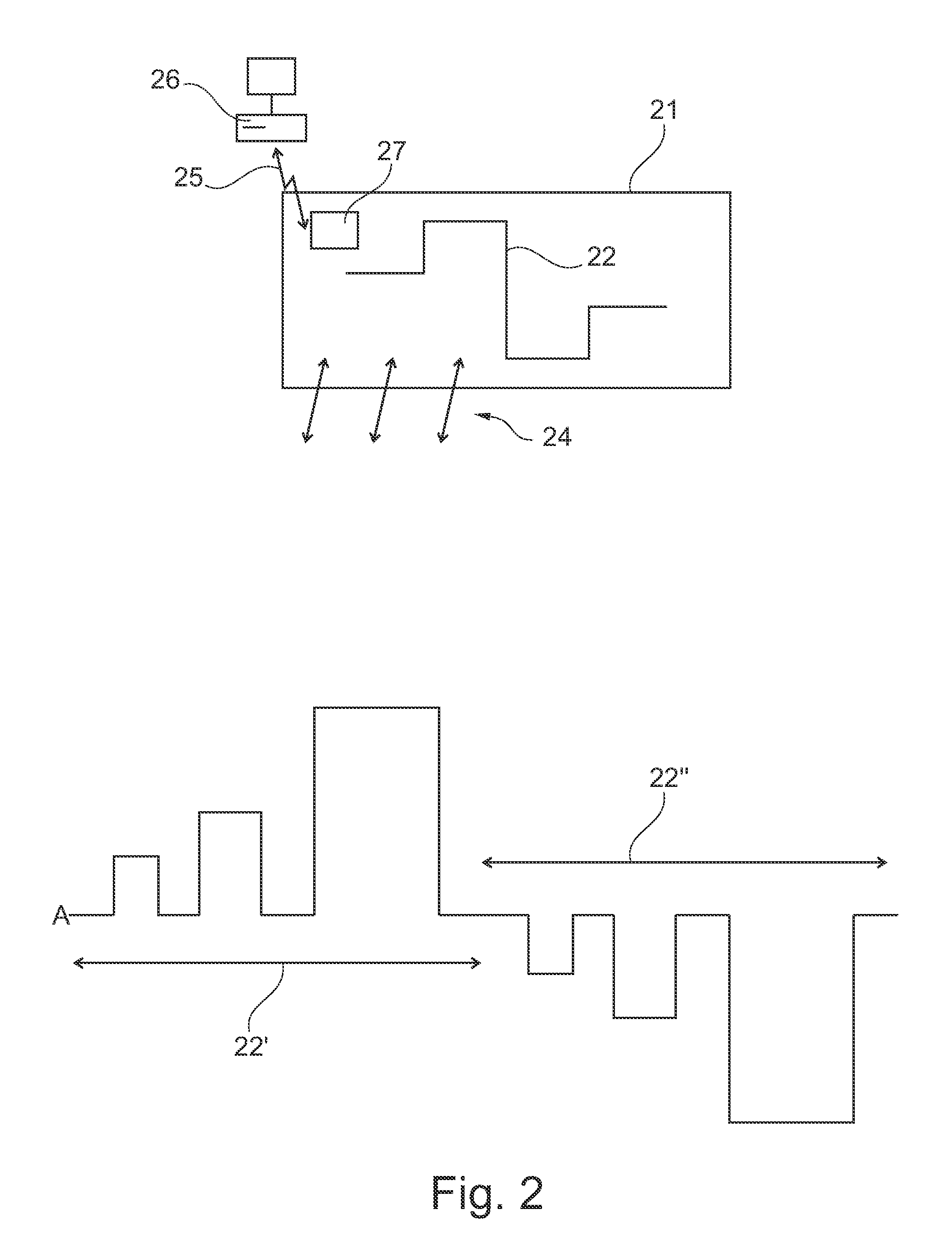
[0189 shows a first sequence 22′ followed by a second sequence 22″.

[0190]Generally, each sequence 22 has an event or a moment period 60 that relates to the magnetic moment 7 and the B / E-measuring unit 12, the recording device 14 by determining the workings and interrelations between these units.

[0191]The moment period 60 has signal level that determines or translates into a moment strength 61 which signal level lasts for a moment period or an on-time period 62 followed by an off-time period 63. The on-time period 62 and the off-time period 63 at least constitute a sequence period 64.

[0192]It is during a sequence period 64 that the magnetic moment 7 is established and that the magnetic field 10 is build up in the formation 2 and measured by the B / E-measuring unit 12 and various recordings 17, 18, 19, 20 are made by the recording device 14 according to the disclosure and the general knowledge of the person skilled in the art.

[0193]The first sequence 22′ has a signal level that determi...

example c

[0209 shows a first sequence 22′ and a second sequence 22″.

[0210]The first sequence 22′ lasts a sequence period 64′ and has multiple on-time periods 62′A, 62′B, 62′C with signal levels resulting in increasing magnetic moment strengths 61′A61′B61′C each followed by increasing off-time periods 63′A63′B63′C. In short the firs sequence fires multiple magnetic moments 7′A, 7′B, 7′C increasing in size.

[0211]The first sequence 22′ is followed by a second sequence 22″ lasting a sequence period 64″. In this embodiment, the second sequence 22″ is identical to the first sequence 22′ except that the signal levels are of opposite signs thereby resulting in multiple magnetic moments 7″A, 7″B, 7″C.

[0212]According to some embodiments, the two sequences 22′, 22″ are executed within a period less than 1 second. In one embodiment there can be a time delay between the two sequences 22′, 22″.

[0213]According to some embodiments, the two sequences 22′, 22″ are executed at different times, but within a dis...

example d

[0215 shows sequences resulting from measuring equipment or a method for mapping the geological structure configured to perform a first sequence with moments with moment strengths 61′ arranged so that the moment strengths 61′A61′B61′C are followed by similar subsequence with moments of the same moment strengths, but with opposite signs / orientations 61′D>61′E>61′F.

[0216]The sub-sequences 61′A61′B61′C and 61′D>61′E>61′F are timed so as to cancel out contributions from the grid periods such as 50 or 60 Hz according to the location of using the measuring equipment or performing the measuring method.

[0217]The first sequence 22′ is followed by a second sequence 22″ with identical moments as those moments in the first sequence 22′.


PUM


Abstract

A method for mapping geological structures of a formation on a side of a surface, includes: generating a magnetic moment using at least one magnetic moment generator to build up a magnetic field in the formation in an on-period, wherein the magnetic moment has a moment strength, and wherein the magnetic moment is positioned on another side of the surface; changing the magnetic moment to change the magnetic field; and making at least one record in a recording device at a recording time trecord in an off-period, wherein the record includes at least a representation of the change in the magnetic field and / or a representation of the magnetic field obtained by a B / E-measuring unit; wherein the on-period is separated from the off-period by the act of changing the magnetic moment.

Description

RELATED APPLICATION DATA[0001]This application is the national phase of International Patent Application No. PCT / DK2012 / 050168, filed on May 14, 2012, pending, which claims priority to Danish Patent Application No. PA 2011 70327, filed on Jun. 24, 2011. The entire disclosures of both of the above applications are expressly incorporated by reference herein.FIELD AND BACKGROUND[0002]The present disclosure relates to a method for mapping a geological structure of a formation on one side of a surface.SUMMARY[0003]The present disclosure relates to a method for mapping a geological structure of a formation on one side of a surface, and comprising a sequence lasting a sequence period and comprising:[0004]an on-period where a magnetic field is built up in the said formation by generating a magnetic moment, which magnetic moment has a moment strength, using at least one transmitter coil, which is positioned on the other side of the surface at a given position, which on-period is separated fr...

Claims


Application Information

Patent Timeline
IPC IPC(8): G01V3/08
CPCG01V3/10G01V3/16G01V3/08
Inventor SORENSEN, KURT INGVARD
Owner SKYTEM SURVEYS APS
Learn More