Planar waveguide laser pumping module and planar waveguide wavelength conversion laser device
a laser device and laser pumping technology, applied in the direction of optics, instruments, active medium materials, etc., can solve the problems of high brightness and high power light sources required by projectors, and achieve high beam overlap efficiency, high output power, and high output power.
- Summary
- Abstract
- Description
- Claims
- Application Information
AI Technical Summary
Benefits of technology
Problems solved by technology
Method used
Image
Examples
embodiment 1
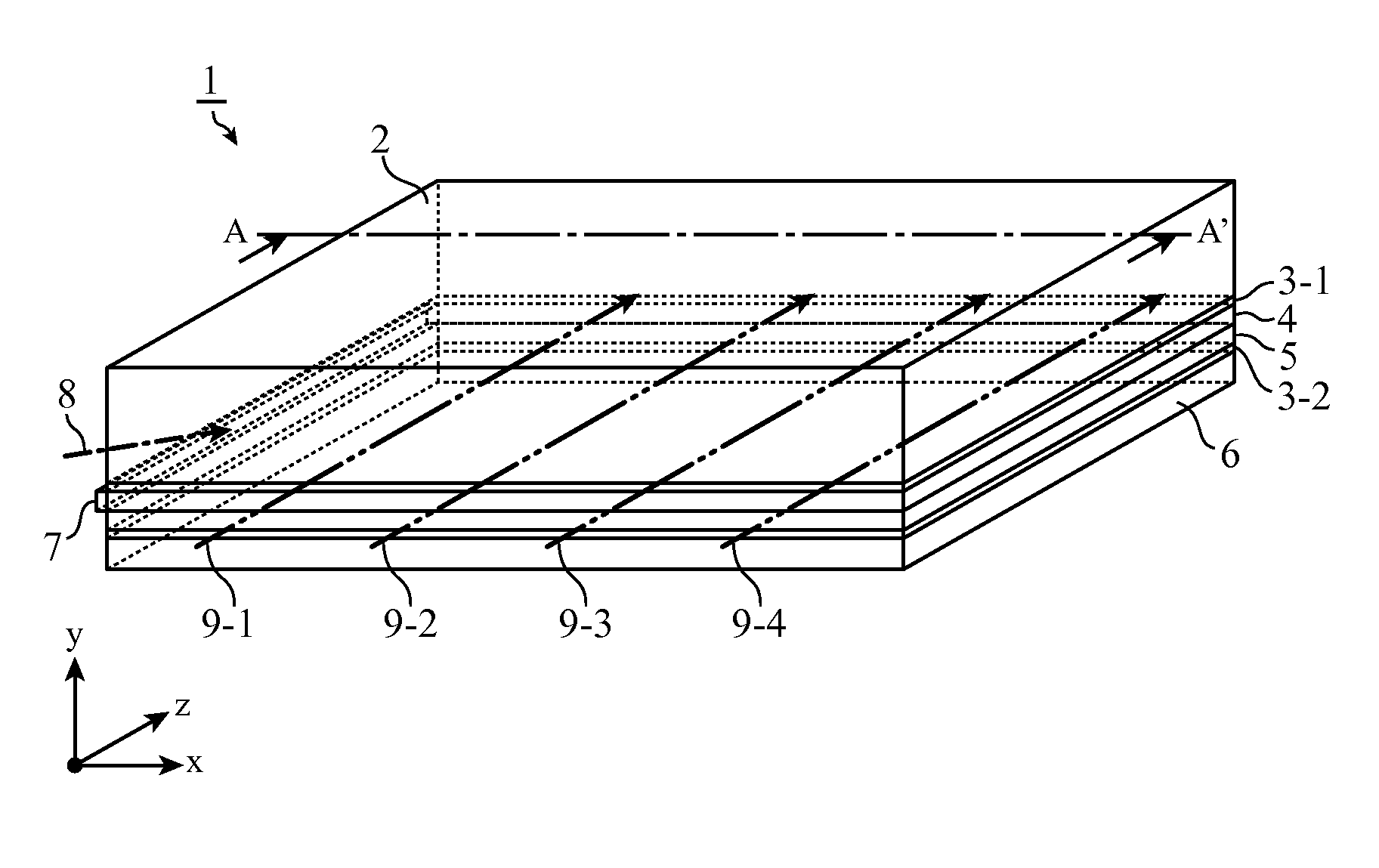
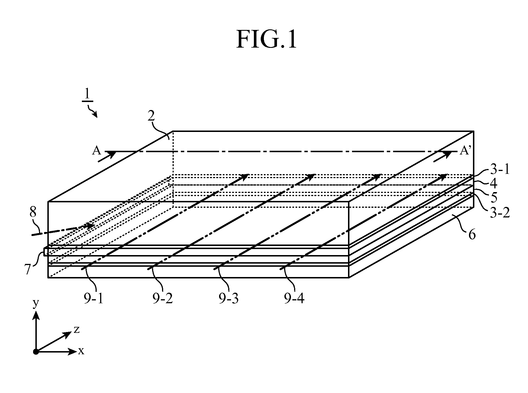
[0028]As shown in FIG. 1, in a planar waveguide laser pumping module 1 in accordance with this Embodiment 1, a reinforcement board 2, a first clad 3-1, a transparent member 4, a laser medium 5, a second clad 3-2, and a heat sink 6 are laminated in a direction of the thickness, and an end surface 4a of the transparent member 4 upon which pumping light 8 is incident is covered by a pumping light antireflection member 7. In the figure, a dashed dotted line denotes the pumping light 8, and chain double-dashed lines denote first to fourth laser oscillation light beams 9-1 to 9-4.
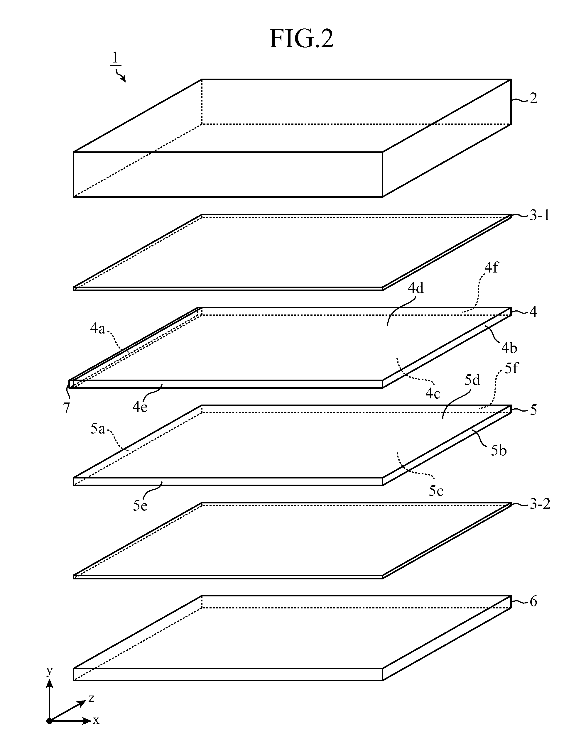
[0029]A perspective view in which the planar waveguide laser pumping module 1 in accordance with this Embodiment 1 is exploded in the thickness direction is shown in FIG. 2. Hereafter, for purposes of illustration, a direction of the optical axis of the pumping light 8 is defined as x, the thickness direction of the planar waveguide laser pumping module 1 is defined as y, and a direction of the optical axis of ea...
embodiment 2
[0074]FIG. 5 is an appearance perspective view showing the structure of a planar waveguide laser pumping module 11 in accordance with this Embodiment 2, and FIG. 6 is an exploded perspective view of the module. As shown in FIGS. 5 and 6, in the planar waveguide laser pumping module 11 in accordance with this Embodiment 2, a reinforcement board 2, a first clad 3-1, a transparent member 4, a laser medium 5, a second clad 3-2, and a heat sink 16 are laminated in a direction y of the thickness, and an end surface 4a of the transparent member 4 upon which pumping light 8 is incident is covered by a pumping light antireflection member 7. In the figures, a dashed dotted line denotes the pumping light 8, and chain double-dashed lines denote first to fourth laser oscillation light beams 9-1 to 9-4.
[0075]Because the structure of the planar waveguide laser pumping module 11 in accordance with this Embodiment 2 is the same as that of the planar waveguide laser pumping module 1 in accordance wit...
embodiment 3
[0088]FIG. 8 is an appearance perspective view showing the structure of a planar waveguide laser pumping module 21 in accordance with Embodiment 3, and FIG. 9 is an exploded perspective view of the module. As shown in FIGS. 8 and 9, in the planar waveguide laser pumping module 21 in accordance with this Embodiment 3, a reinforcement board 2, a first clad 3-1, a transparent member 24, a laser medium 25, a second clad 3-2, and a heat sink 16 are laminated in a direction y of the thickness, and an end surface 24a of the transparent member 24 upon which pumping light 8 is incident is covered by a pumping light antireflection member 7. In the figures, a dashed dotted line denotes the pumping light 8, and chain double-dashed lines denote first to fourth laser oscillation light beams 9-1 to 9-4.
[0089]Because the structure of the planar waveguide laser pumping module 21 in accordance with this Embodiment 3 is the same as that of the planar waveguide laser pumping module 11 in accordance wit...
PUM
 Abstract
Description
Claims
Application Information
 - R&D
- Intellectual Property
- Life Sciences
- Materials
- Tech Scout
- Unparalleled Data Quality
- Higher Quality Content
- 60% Fewer Hallucinations
Browse by: Latest US Patents, China's latest patents, Technical Efficacy Thesaurus, Application Domain, Technology Topic, Popular Technical Reports.
© 2025 PatSnap. All rights reserved.Legal|Privacy policy|Modern Slavery Act Transparency Statement|Sitemap|About US| Contact US: help@patsnap.com


