projector
a projector and optical element technology, applied in the field of projectors, can solve the problems of degrading display quality, insufficient effect for reducing speckles obtained by providing only equalizing optical elements, etc., and achieve the effect of reducing speckles and reducing variations in illuminance distribution
- Summary
- Abstract
- Description
- Claims
- Application Information
AI Technical Summary
Benefits of technology
Problems solved by technology
Method used
Image
Examples
first embodiment
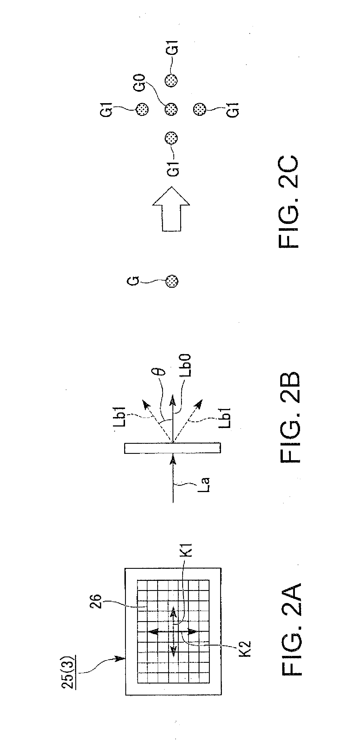
[0031]Hereinafter, a first embodiment of the invention will be explained using FIGS. 1, 2A, 2D, 2C, 3A, 3B, 3C, 4A, and 4B.
[0032]In the present embodiment, an example of a projector using an illumination device provided with a laser source will be described.
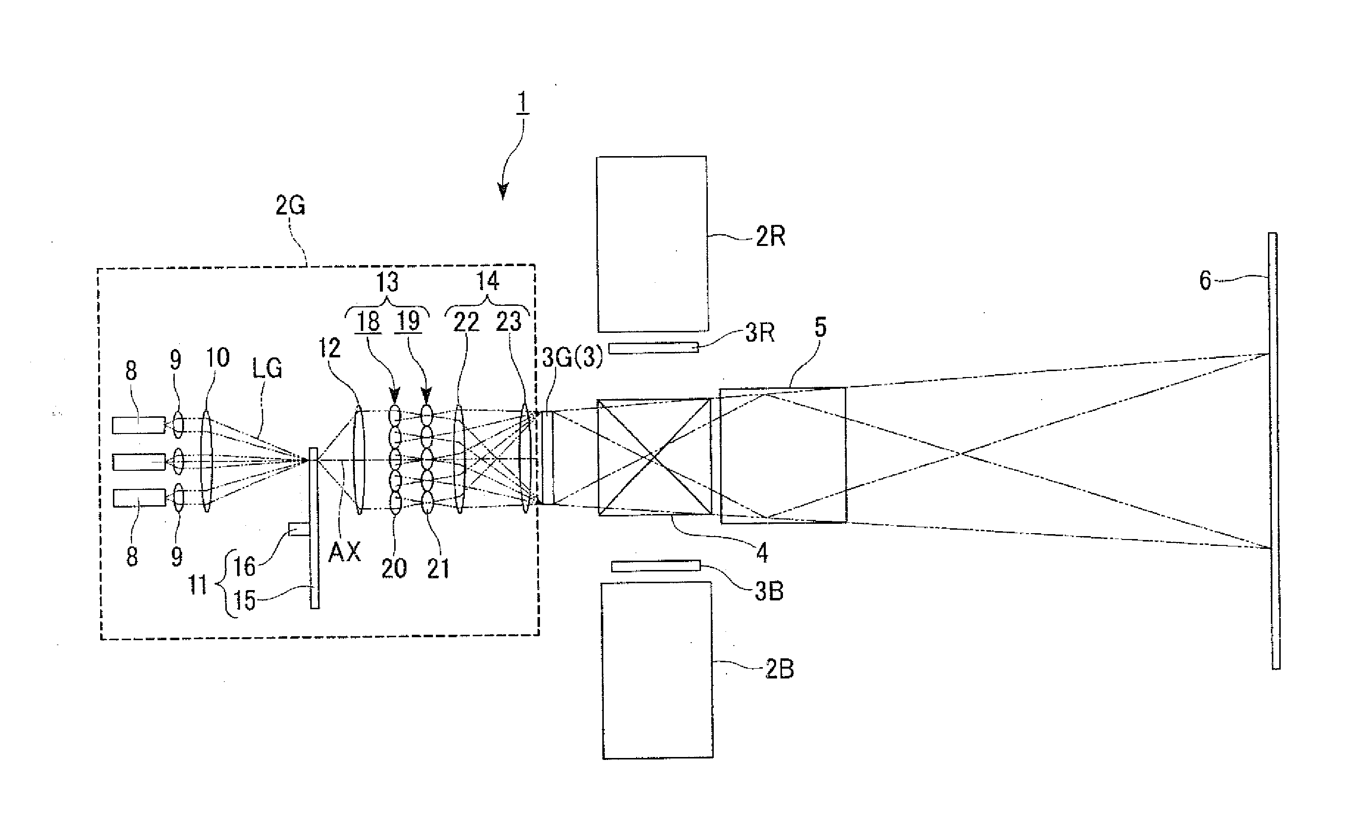
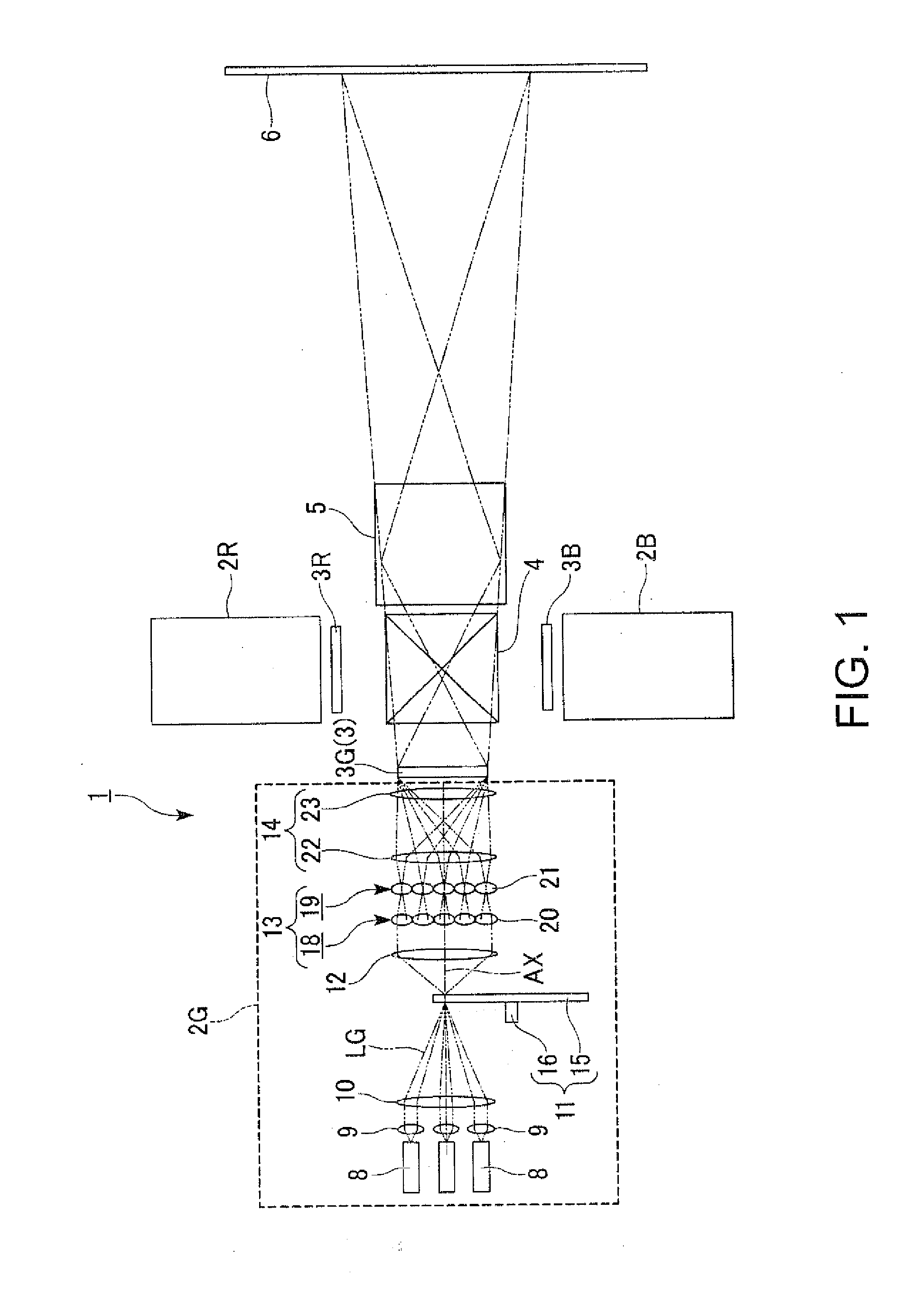
[0033]FIG. 1 is a schematic configuration diagram showing the projector according to the first embodiment.
[0034]It should be noted that in each the following drawings, the constituents are shown with the scale ratios of respective sizes set differently between the constituents in some cases in order to facilitate the visualization of each of the constituents.
[0035]As shown in FIG. 1, the projector 1 is provided with a red-light illumination device 2R, a green-light illumination device 2G, a blue-light illumination device 2B, a red-light liquid crystal light valve 3R, a green-light liquid crystal light valve 3G, a blue-light liquid crystal light valve 3B, a color combining element 4, and a projection optical system 5.
[0036]The red...
second embodiment
[0068]A second embodiment of the invention will hereinafter be explained using FIGS. 5 through 7.
[0069]The basic configuration of a projector 31 according to the second embodiment is roughly the same as that in the first embodiment, and the configuration of the illumination device is different from that of the first embodiment.
[0070]FIG. 5 is a schematic configuration diagram showing the projector 31 according to the second embodiment.
[0071]In FIG. 5, the constituents common to FIG. 1 used in the description of the first embodiment are denoted with the same reference symbols, and the detailed explanation thereof will be omitted.
[0072]As shown in FIG. 5, a green-light illumination device 32G of the second embodiment emits a plurality of green light beams, which include a first light beam and a second light beam, as the illumination light. The green-light illumination device 32G is provided with the plurality of laser sources 8, the plurality of collimating lenses 9, a diffractive opt...
third embodiment
[0077]A third embodiment of the invention will hereinafter be explained using FIGS. 8 and 9. The basic configuration of a projector according to the third embodiment is roughly the same as that in the first embodiment, and the configuration of the illumination device is different from that of the first embodiment.
[0078]FIG. 8 is a schematic configuration diagram showing the projector 41 according to the third embodiment. In FIG. 8, the constituents common to FIG. 1 used in the description of the first embodiment are denoted with the same reference symbols, and the detailed explanation thereof will be omitted.
[0079]As shown in FIG. 8, a green-light illumination device 420 of the third embodiment emits a plurality of green light beams, which include a first light beam and a second light beam, as the illumination light. The green-light illumination device 420 is provided with the plurality of laser sources 8, the plurality of collimating lenses 9, the lens array unit 13, and the overla...
PUM
 Abstract
Description
Claims
Application Information
 - R&D
- Intellectual Property
- Life Sciences
- Materials
- Tech Scout
- Unparalleled Data Quality
- Higher Quality Content
- 60% Fewer Hallucinations
Browse by: Latest US Patents, China's latest patents, Technical Efficacy Thesaurus, Application Domain, Technology Topic, Popular Technical Reports.
© 2025 PatSnap. All rights reserved.Legal|Privacy policy|Modern Slavery Act Transparency Statement|Sitemap|About US| Contact US: help@patsnap.com


