
Projection display surface providing speckle reduction

a projection display and projection screen technology, applied in projectors, color television details, instruments, etc., can solve the problems of narrow band light source systems, reduce the ability of imaging systems to resolve, and reduce the effective quality of images, so as to reduce the effect of speckle and reduce the impact of image quality

Active Publication Date: 2011-12-27
IMAX THEATERS INT
View PDF32 Cites 32 Cited by
  • Summary
  • Abstract
  • Description
  • Claims
  • Application Information

AI Technical Summary

Benefits of technology

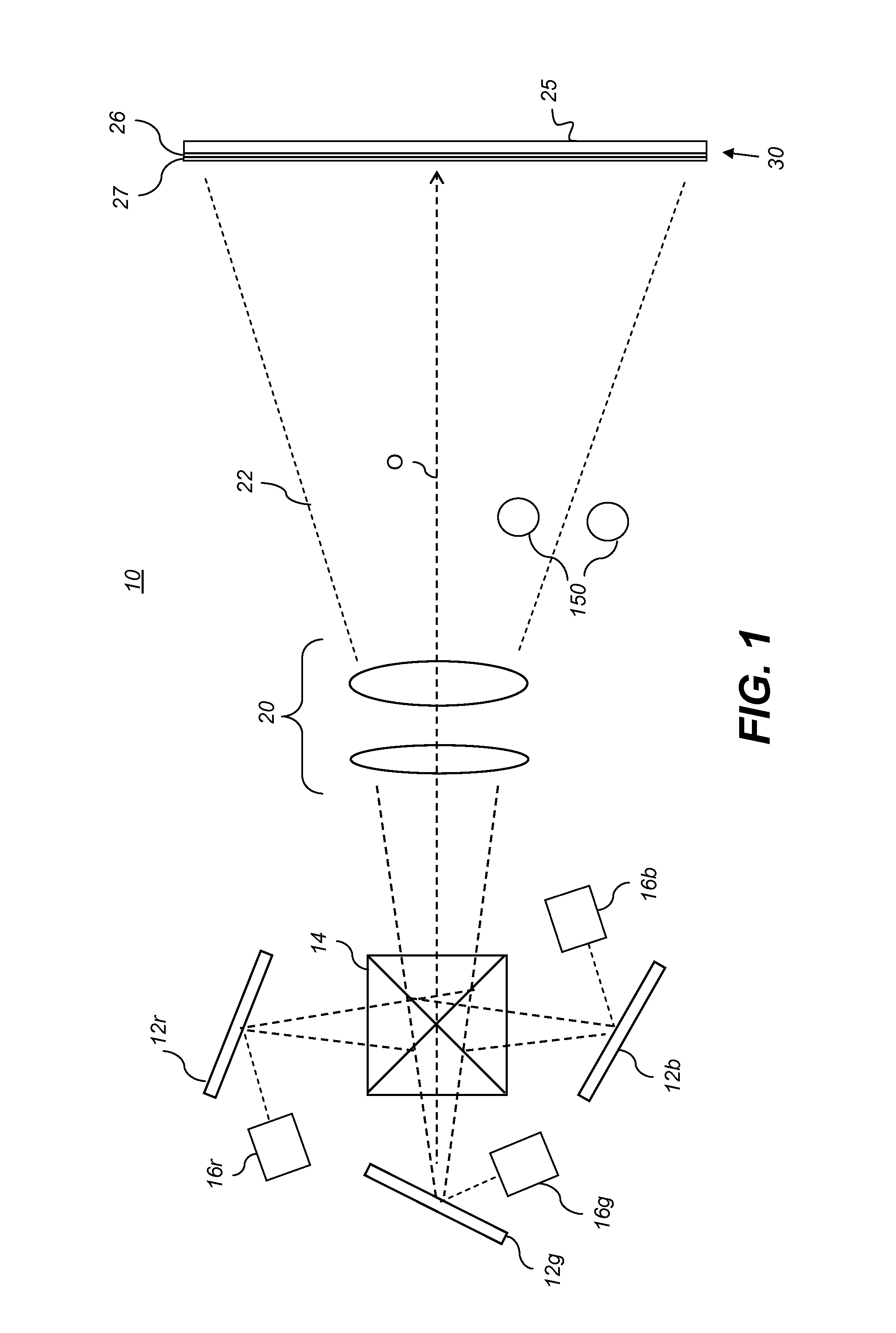
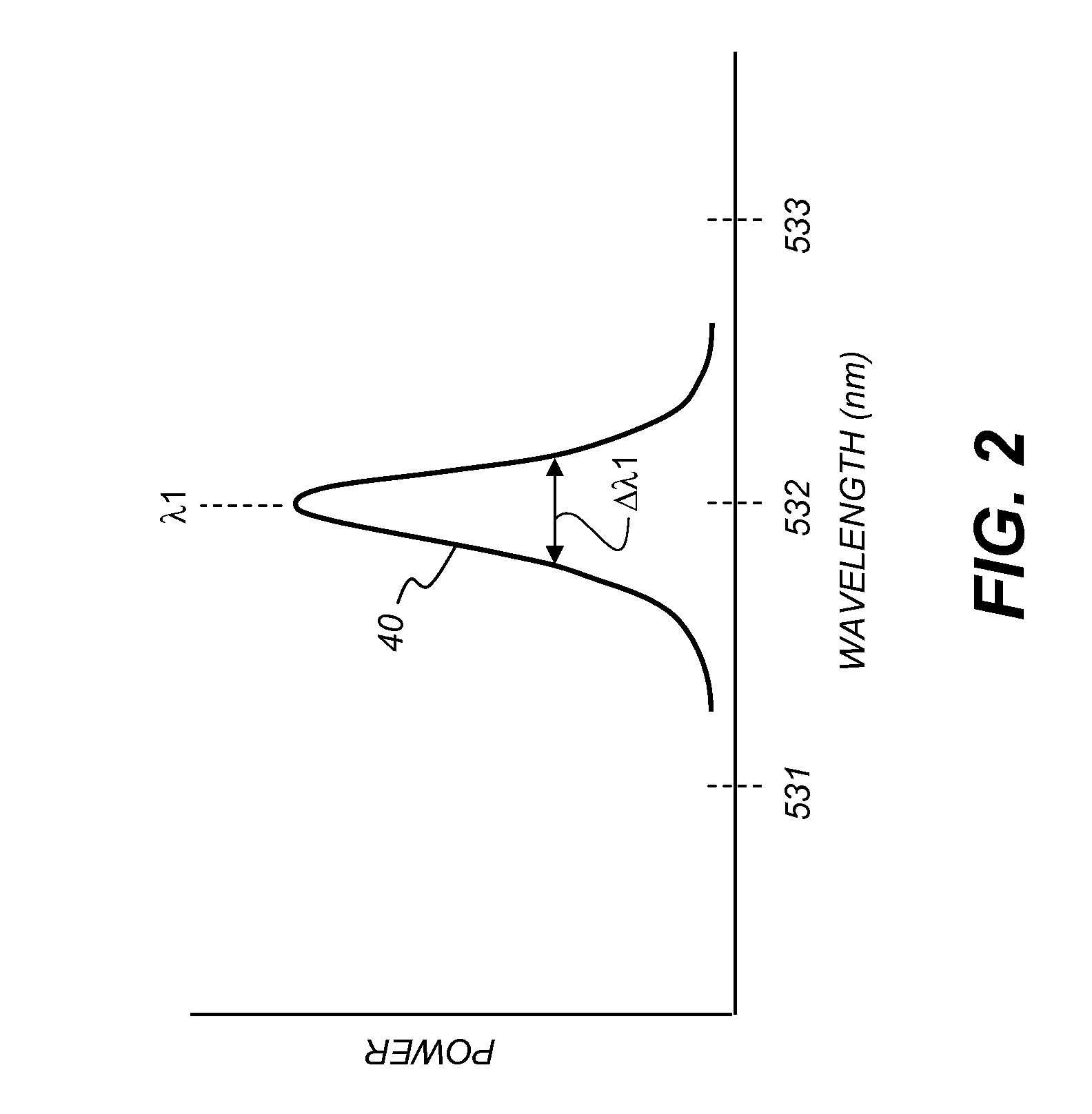
The present invention is about improving digital image projection by reducing speckle artifacts. This is achieved by using a projection display surface that includes a reflective layer and a fluorescent agent distributed over the reflective layer. The reflective layer reflects incident light over at least the incident visible wavelength band, while the fluorescent agent absorbs a fraction of the light in the incident visible wavelength band and emits light in an emissive visible wavelength band having an emissive peak wavelength and an emissive bandwidth that is wider than the incident bandwidth. The return light from the projection display surface contains light in both the incident and emissive visible wavelength bands, resulting in reduced speckle artifacts through spectral broadening. The invention is independent of the image-forming technology used in the projector and does not add any cost or complexity. It also reduces speckle with little impact on image quality.

Problems solved by technology

One recognized problem with projection systems using narrow band light sources, however, relates to speckle.
The increased coherence of lasers introduces a significant effect in projection systems where the roughness creates randomly phased sub-sources, which interfere together.
This random intensity fluctuation lowers the effective quality of an image, especially at the higher frequencies essentially producing a “shimmer effect” that masks fine details, but also creating an intensity sharpness that is really artificial.
Speckle reduces the ability of an imaging system to resolve fine spatial detail and causes levels of noise in an image that can be highly visually annoying.
At worst, without some form of correction, speckle can be sufficiently objectionable to render coherent illumination unsuitable for display purposes.
In addition, in many cases a single approach may not be effective enough to reduce the speckle below acceptable thresholds.
For example, polarization diversity is not desirable in many cases, as any projector that requires polarization either to modulate the light or to create stereoscopic imaging cannot allow impure states to reach the viewer.
Specially designed screens that enable screen shaking can be effective, however, they require significant modification to the venue that is undesirable.
Large screens are especially difficult to modify to enable screen shaking, as the equipment is large and expensive.
Spectrally broadening of the light sources can substantially reduce the level of speckle, however, this may be difficult to control in the laser fabrication, as many methods of creating visible solid state sources desired for display applications use frequency double crystals that control the wavelength to around 1 nm.
As described earlier, increasing the number of lasers is effective at reducing speckle, however the effect is incomplete.
The additional methods described are generally difficult to implement, expensive or undesirable optically.
This is undesirable for general projection purposes.
This method requires laser modulation that may not be practical or possible for all laser sources.
These devices are very expensive and can only handle certain laser types and sizes.
While conventional methods for speckle reduction may have some applicability to laser-based projection systems, there are drawbacks to these approaches that constrain image quality and reduce overall contrast as well as adding cost and complexity to projection apparatus.
Any type of modification to components in the imaging path, for example, can require significant redesign, can complicate component packaging, and risks the introduction of noise or vibration into optical and signal paths of projector components.
The problem of speckle reduction is further complicated because different types of spatial light modulators (SLMs) are being used for digital projection.
However, they present problems due to the energy density that can be delivered which limits the amount of light that can safely be projected.
Because images are formed in different ways using these different SLMs and projection technologies, solutions that compensate for speckle with one type of SLM may not be as effective when used in a projector that uses a different type of SLM for forming images.
Conventional speckle compensation approaches add cost and complexity to projector design, and generally reduce image quality with respect to projector output.

Method used


Image

  • Projection display surface providing speckle reduction
  • Projection display surface providing speckle reduction
  • Projection display surface providing speckle reduction

Examples


Embodiment Construction

[0062]For the detailed information that follows, it is to be understood that elements not specifically shown or described may take various forms well known to those skilled in the art. Figures shown and described herein are provided to illustrate key principles of operation and component relationships along their respective optical paths according to embodiments of the present invention and may not show actual size or scale. Some exaggeration may be necessary in order to emphasize basic structural relationships or principles of operation.

[0063]Embodiments of the present invention address the problem of speckle reduction by adapting the response of a display screen or other type of display surface to incident narrow band light from a projector. By redistributing a portion of the incident light energy to emissive materials on the display screen surface, embodiments of the present invention effectively expand the spectral bandwidth of the displayed image, thereby reducing speckle artif...


PUM


Abstract

A projection display surface for reducing speckle artifacts from a projector having at least one narrow band light source having an incident visible wavelength band, wherein the incident visible wavelength band has an incident peak wavelength and an incident bandwidth, comprising: a substrate having a reflective layer that reflects incident light over at least the incident visible wavelength band; and a fluorescent agent distributed over the reflective layer, wherein the fluorescent agent absorbs a fraction of the light in the incident visible wavelength band and emits light in an emissive visible wavelength band having an emissive peak wavelength and an emissive bandwidth; wherein return light from the projection display surface produced when incident light in the incident visible wavelength band is incident on the projection display surface contains light in both the incident visible wavelength band and emissive visible wavelength band, thereby reducing speckle artifacts.

Description

CROSS-REFERENCE TO RELATED APPLICATIONS[0001]Reference is made to commonly assigned, co-pending U.S. patent application Ser. No. 12 / 816,579, entitled: “Projection Apparatus Providing Reduced Speckle Artifacts”, by Barry Silverstein et al., which is incorporated herein by reference.FIELD OF THE INVENTION[0002]The present invention relates generally to digital image projection and more particularly to a laser projector with a projection screen containing fluorescent materials to reduce the speckle noise in the displayed image.BACKGROUND OF THE INVENTION[0003]Laser illumination shows some promise for improving color gamut and achieving needed levels of brightness for digital projection apparatus, including digital projectors capable of providing cinema-quality imaging and pico-projectors offering portable projection for easier sharing of images. One recognized problem with projection systems using narrow band light sources, however, relates to speckle.[0004]Speckle is a fine scale spat...

Claims


Application Information

Patent Timeline
Patent Type & Authority Patents(United States)
IPC IPC(8): G03B21/56G03B21/26
CPCG03B21/60H04N9/3132G03B33/16
Inventor SILVERSTEIN, BARRY D.MARCUS, MICHAEL A.KURTZ, ANDREW F.
Owner IMAX THEATERS INT
Learn More