
Phosphor and light emitting device using the same

Active Publication Date: 2015-07-30
NICHIA CORP
View PDF9 Cites 15 Cited by
  • Summary
  • Abstract
  • Description
  • Claims
  • Application Information

AI Technical Summary

Benefits of technology

The patent text discusses how researchers have discovered that by adjusting the composition of the raw material used to create a phosphor, they can control the width of the emission spectrum and the peak wavelength. This allows for brighter light to be emitted with less color loss, resulting in a higher luminous flux for light emitting devices.

Problems solved by technology

This was caused by that with this synthesis condition, a stable CASN phosphor can be obtained but a SCASN phosphor cannot be stably exist and is gradually decomposed into different compounds (Sr2SiN5, AlN, or the like), so that a substantially pure SCASN phosphor was not able to be produced.
However, any phosphors and the method of manufacturing those phosphors described above regard merely a synthesis and emission luminance of a SCASN phosphor, and the control of the shape of the emission spectrum by finely controlling the chemical composition has not been examined.

Method used


Image

  • Phosphor and light emitting device using the same
  • Phosphor and light emitting device using the same
  • Phosphor and light emitting device using the same

Examples


examples 11-16

, Comparative Examples 11-12

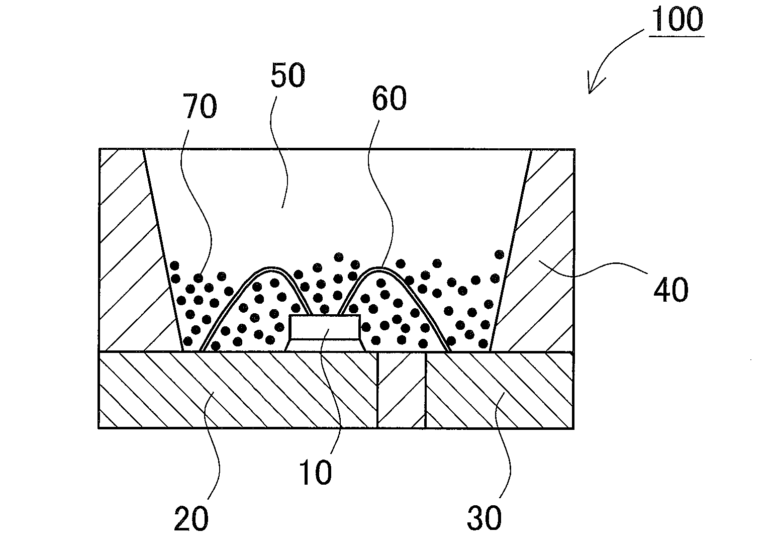
[0095]As described above, it can be expected that a reduction in the half value width of the emission spectrum of a SCASN phosphor can lead an increase in the luminous flux of the light emitting device which employs the phosphor. In order to confirm the above, the phosphors manufactured as described in Comparative Examples 1, 2 and Examples 1 to 6 were respectively combined with an LED which is a semiconductor light emitting element, to fabricate respective light emitting devices which can emit a white mixed color light, and the properties of the light emitting devices were evaluated. For the light emitting device, an LED to emit blue light having an emission peak wavelength of 455 nm and Y3(Al, Ga)5O12:Ce are used in combination. The chromaticity (x, y) and the average color rendering index (Ra) of the light emitting devices are shown in Table 3. As shown in Table 3, the luminous flux value of Comparative Example 11 is set to 100% as reference, the lumin...

examples 17-20

, Comparative Examples 13-16

[0097]In the examples shown above, a case in which one kind of phosphor is combined with an LED to obtain a light emitting device is illustrated, but the present embodiment of the disclosure is not limited thereto, two or more kinds of phosphors can be combined with the LED. In such a case, a first phosphor having a first emission spectrum and a second phosphor having a second emission spectrum which is different from that of the first emission spectrum is preferably combined. With this arrangement, a light emitting device of high flux can be obtained.

[0098]Such examples are made as Examples 17 to 20, and the luminous flux ratio, the chromaticity, and the average color rendering index were measured, and the results are shown in Table 4. The emission spectrum of each of the light emitting device is shown in FIG. 10 to FIG. 13 respectively. In the examples, as the second phosphor to be combined, the phosphors to emit green light: Ca8MgSi4O16Cl2:Eu (Example ...


PUM

PropertyMeasurementUnit
Timeaaaaaaaaaa
Percent by massaaaaaaaaaa

Abstract

A phosphor for absorbing light in a region from ultraviolet to visible light and emitting light whose emission peak wavelength being in a range of 600 nm to 650 nm, represented by general formula shown below, and having a difference between the emission peak wavelength and a half width being larger than 543 nm.SrtCavEuwAlxSiyNz (in which, 0.5≦t<1, 0<v≦0.5, 0.01<w≦0.03, t+v+w<1, 0.90≦x≦1.1, 0.90≦y≦1.1, 2.5≦z≦3.5)

Description

BACKGROUND[0001]1. Technical Field[0002]The present disclosure relates to a phosphor and a light emitting device using the same.[0003]2. Background Art[0004]There have been developed light emitting devices that can emit light of various hues, by using combinations of a light source and a phosphor which can be excited by light from the light source to emit light of different hue than that of the light source, based on the principle of light-color mixing. For example, primary light in a short wavelength region corresponding to ultraviolet light to visible light is emitted from a light emitting element and with the emitted light, a phosphor is excited. As a result, at least a portion of primary light is wavelength-converted, and red, blue, green, or the like, a light of desired color can be obtained. Further, a mixed color light of white light can be emitted by mixing those colors of light.[0005]Light emitting devices employing a light emitting diode (hereinafter may be referred to as ...

Claims


Application Information

Patent Timeline
IPC IPC(8): H01L33/50C09K11/77
CPCC09K11/7734H01L33/502C09K11/7774H01L2224/32245H01L2224/48091H01L2224/48247H01L2224/48257H01L2224/73265Y10T428/2982C09K11/77342C09K11/77348H01L2924/00014H01L2924/00H01L2924/00012
Inventor WATANABE, HIROYUKIHOSOKAWA, SHOJI
Owner NICHIA CORP
Learn More