Electronic module
a technology of electronic modules and modules, applied in the field of electronic modules, can solve problems such as the reliability drop of electronic modules, and achieve the effects of reducing the amount of moisture entering the electronic modules, prolonging the life of the modules, and suppressing the degradation of internal electronic devices
- Summary
- Abstract
- Description
- Claims
- Application Information
AI Technical Summary
Benefits of technology
Problems solved by technology
Method used
Image
Examples
example 1
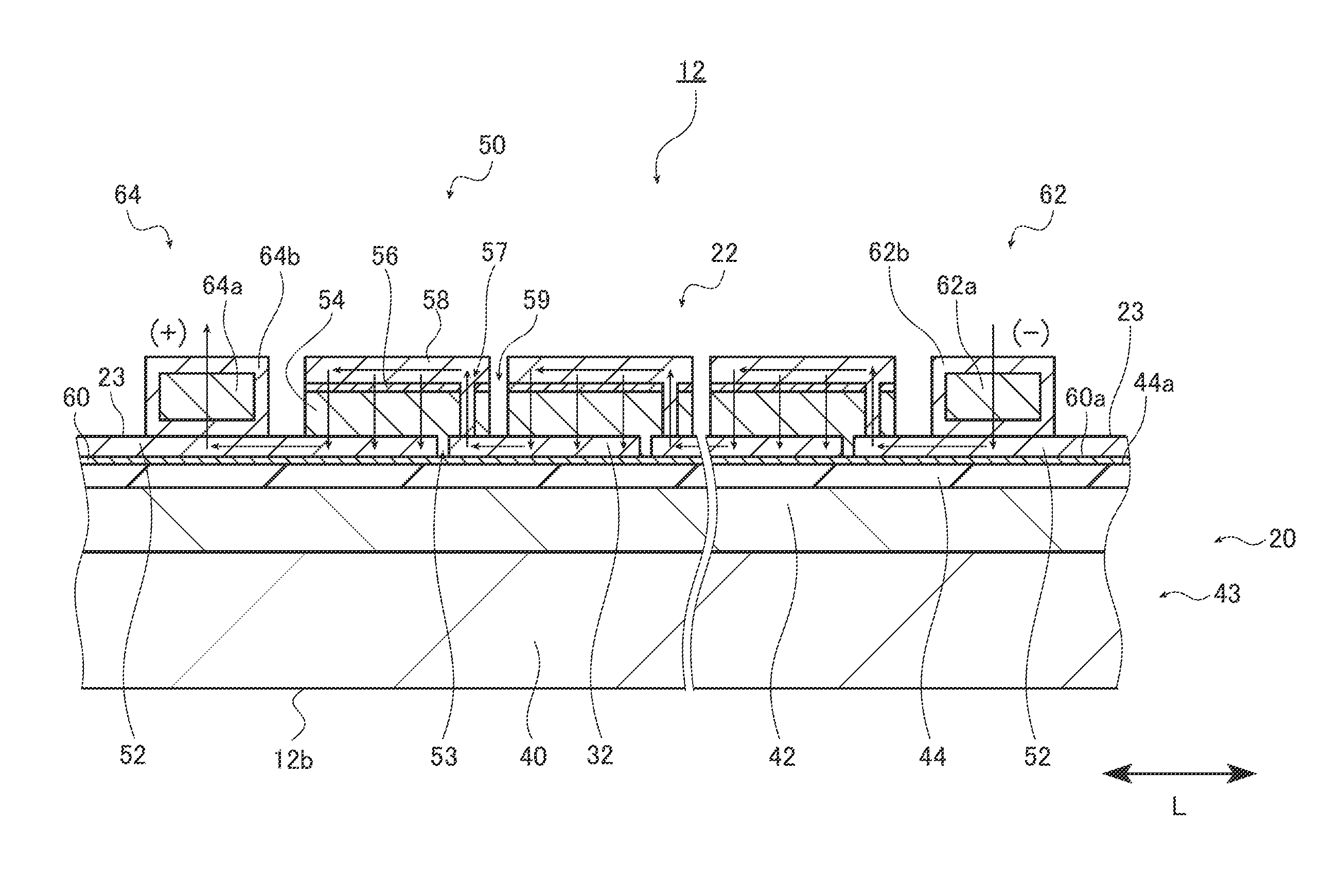
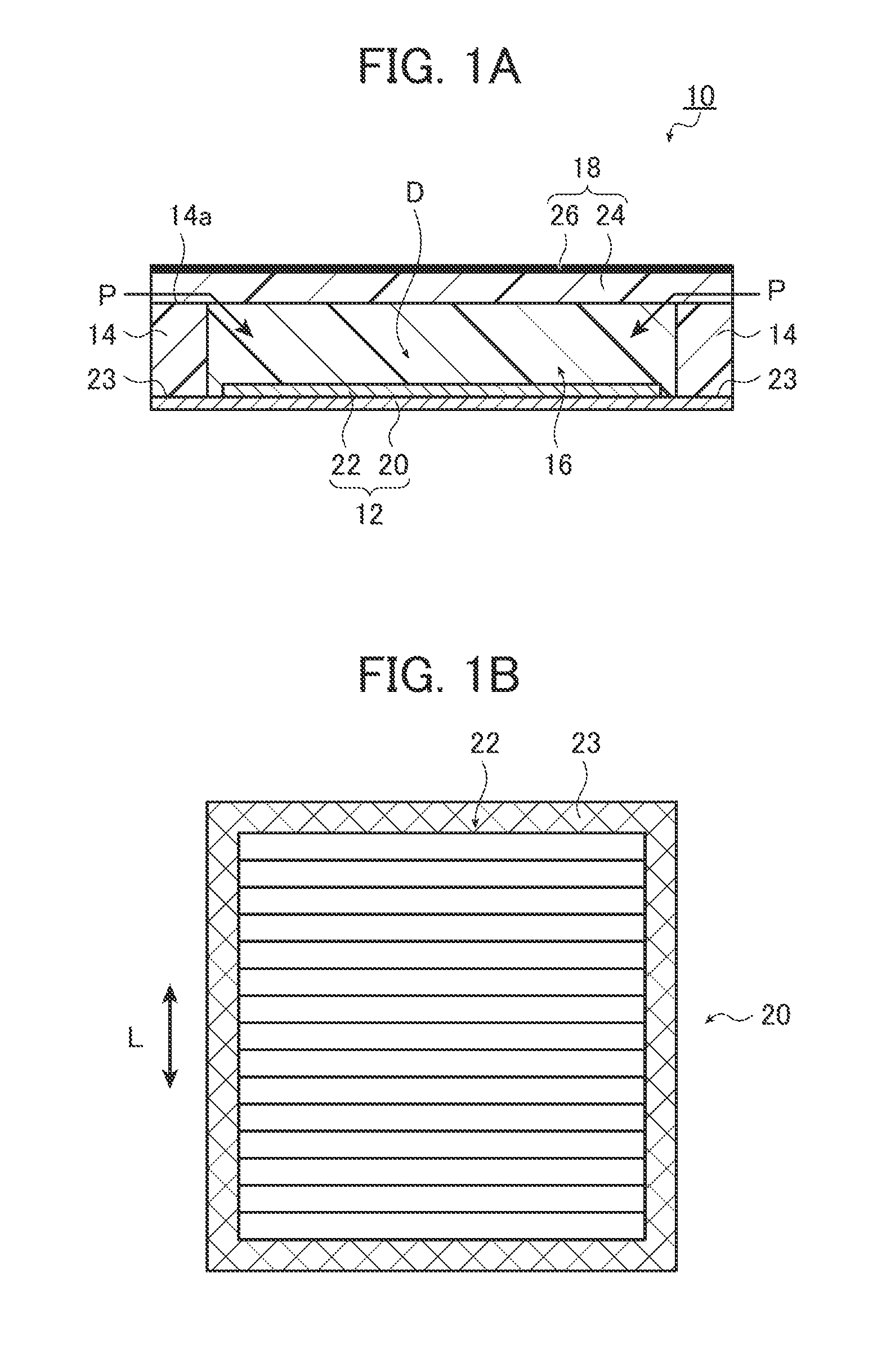
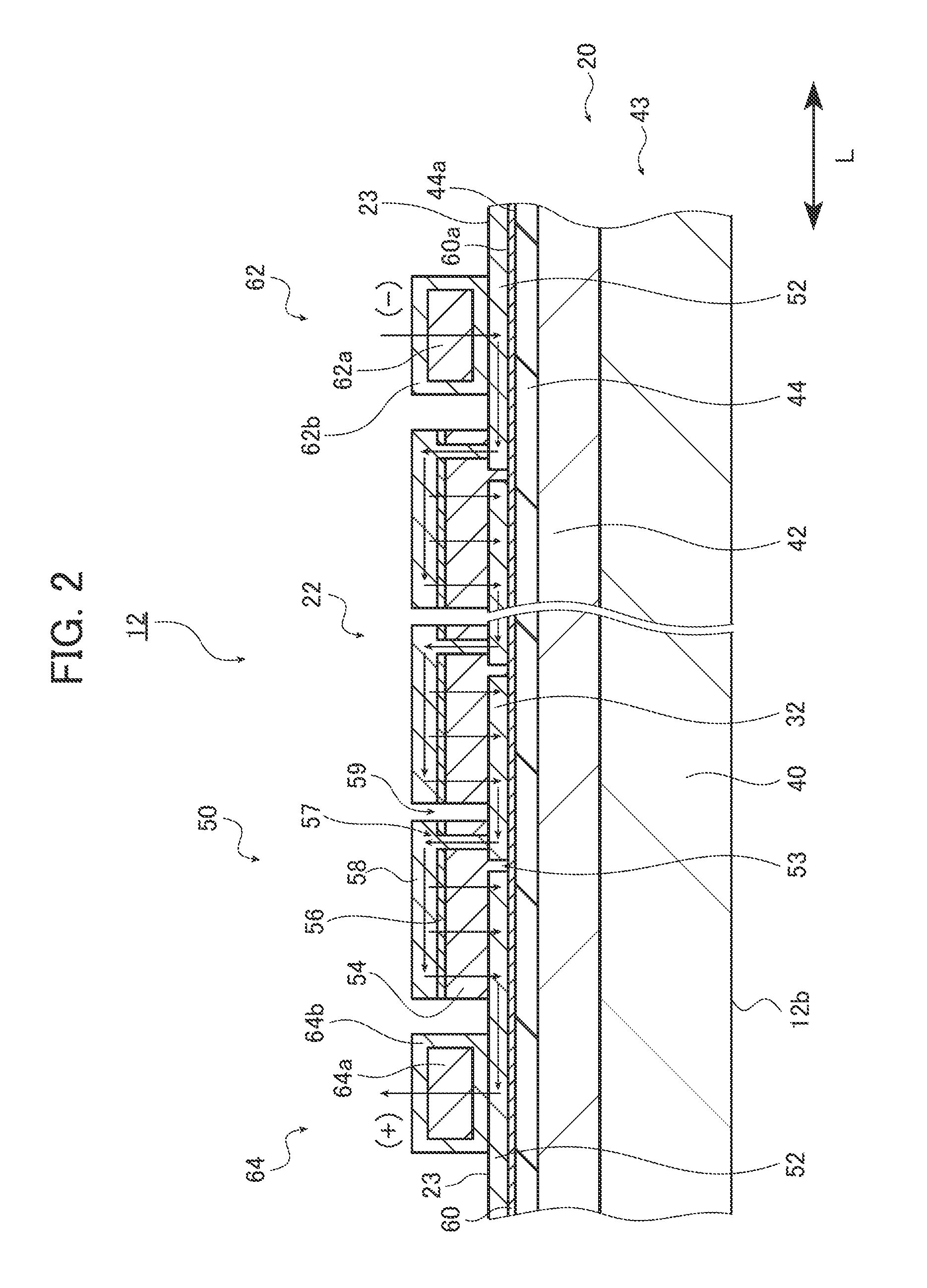
[0158]In Example 1, the electronic module 10 configured as illustrated in FIGS. 1A and 1B, having the CIGS solar battery submodule illustrated in FIG. 2, serves as the electronic device.
[0159]In Example 1, a substrate configured by forming a 10 μm-thick anodic oxide film as the insulating layer 44 on the surface of a clad member of Al (40 μm thick) / SUS (70 μm thick) / Al (40 μm thick) was used as the flexible substrate 20. The size of the flexible substrate was 30 cm×30 cm.
[0160]A liquid mixture of sodium silicate (Na2O.nSiO2.xH2O n=3 to 3.3), lithium silicate, and boric acid (H3BO3) was fired to form a 200 nm-thick, Na-containing glass layer as the alkali supply layer 60 on the surface of the anodic oxide film.
[0161]A 200 nm-thick Mo film was formed as the lower electrodes 52 through sputtering. Then, the solar battery cells 50 were manufactured by layering the photoelectric conversion layer 54 made of a CIGS semiconductor compound, the buffer layer 56, and the upper electrodes 58 on...
example 2
[0177]In this example, the effects of the diffusion coefficient of the edge sealant was confirmed.
[0178]In this example, a 5 cm×5 cm glass plate 70, illustrated in FIG. 5A, is used. As illustrated in FIG. 5B, a 1 cm-wide edge sealant 74 is disposed on an edge portion 72 of the glass plate 70, and a Ca deposition plate 78 is disposed on a surface 76 of the glass plate 70 surrounded by the edge sealant 74. The glass plate 70 illustrated in FIG. 5A is then laminated so as to cover the Ca deposition plate 78, and a test piece 80 is prepared as a result.
[0179]The test piece 80 was moved to an atmosphere having a temperature of 85° C. and a relative humidity of 85% and left for 1,000 h; a suppressive effect was determined to be present in the case where the Ca in the Ca deposition plate 78 did not fade, whereas a suppressive effect was determined to be insufficient in the case where the Ca showed fading. In Table 1, a suppressive effect being present is indicated as “good”, whereas a supp...
example 3
[0182]In this example, electronic modules according to Experimental Examples 1 to 4 indicated below were manufactured and the moisture transmission rate was evaluated 10 times; the moisture ingress suppression was evaluated by confirming how many times a moisture suppression effect was achieved. The results are shown in Table 2.
[0183]As in Example 1, a substrate on which Ca was deposited before sealing was disposed on the solar battery submodule and the water vapor transmission rate was measured in an atmosphere having a temperature of 40° C. and a relative humidity of 90%, using the method disclosed in the aforementioned Document A. As such, detailed descriptions thereof will be omitted.
PUM
| Property | Measurement | Unit |
|---|---|---|
| thick | aaaaa | aaaaa |
| thickness | aaaaa | aaaaa |
| temperature | aaaaa | aaaaa |
Abstract
Description
Claims
Application Information
 - R&D
- Intellectual Property
- Life Sciences
- Materials
- Tech Scout
- Unparalleled Data Quality
- Higher Quality Content
- 60% Fewer Hallucinations
Browse by: Latest US Patents, China's latest patents, Technical Efficacy Thesaurus, Application Domain, Technology Topic, Popular Technical Reports.
© 2025 PatSnap. All rights reserved.Legal|Privacy policy|Modern Slavery Act Transparency Statement|Sitemap|About US| Contact US: help@patsnap.com


