
Wireless charge and discharge wrist band for placing cell phone

a wristband and cell phone technology, applied in the direction of bracelets, substation equipment, transmission, etc., can solve the problems of limited range for the user to use the cell phone, cell phone may have a shortage of power, and the cell phone needs electricity, so as to enhance the safety of using the cell phone and facilitate the use of the cell phon

Inactive Publication Date: 2015-07-09
COREMATE TECH CO LTD
View PDF5 Cites 26 Cited by
  • Summary
  • Abstract
  • Description
  • Claims
  • Application Information

AI Technical Summary

Benefits of technology

The present invention is a wireless charge and discharge wrist band for placing a cell phone. The band is convenient and easy to carry and use. It uses electromagnetic induction to transmit power to the phone, allowing it to be charged anywhere and at any time. This improves the safety and convenience of using the phone. The band is also designed to enhance the user experience by integrating the watch seat with the charge coil and power supply coil for the band to combine with the wireless charging device. This allows for seamless power transmission and use of the phone with the band. Overall, the invention provides a convenient and safe way to carry and use a cell phone while ensuring optimal performance.

Problems solved by technology

However, the cell phone needs electricity when in use.
By using the wired power supply device to proceed with power transmission for the cell phone, the range for the user to use the cell phone is limited to where the wired poser supply device is located.
During using the cell phone, the cell phone may have a shortage of power.
This is not convenient for operation.
In addition, the connection of the cell phone and the wired power supply device may have the risk of electric leakage.

Method used


Image

  • Wireless charge and discharge wrist band for placing cell phone
  • Wireless charge and discharge wrist band for placing cell phone
  • Wireless charge and discharge wrist band for placing cell phone

Examples


Embodiment Construction

[0014]Embodiments of the present invention will now be described, by way of example only, with reference to the accompanying drawings.

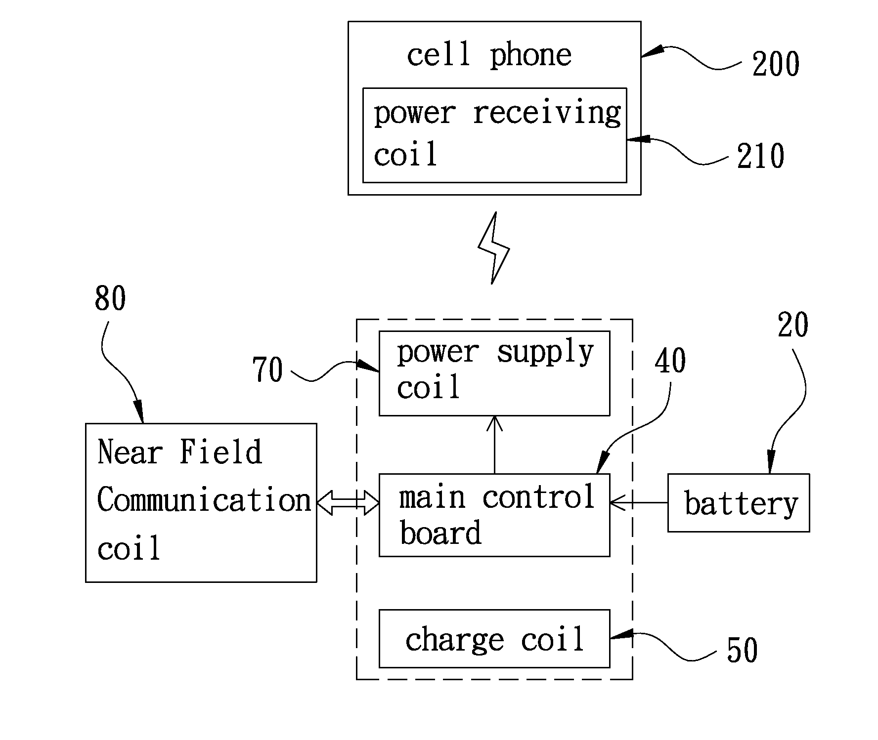
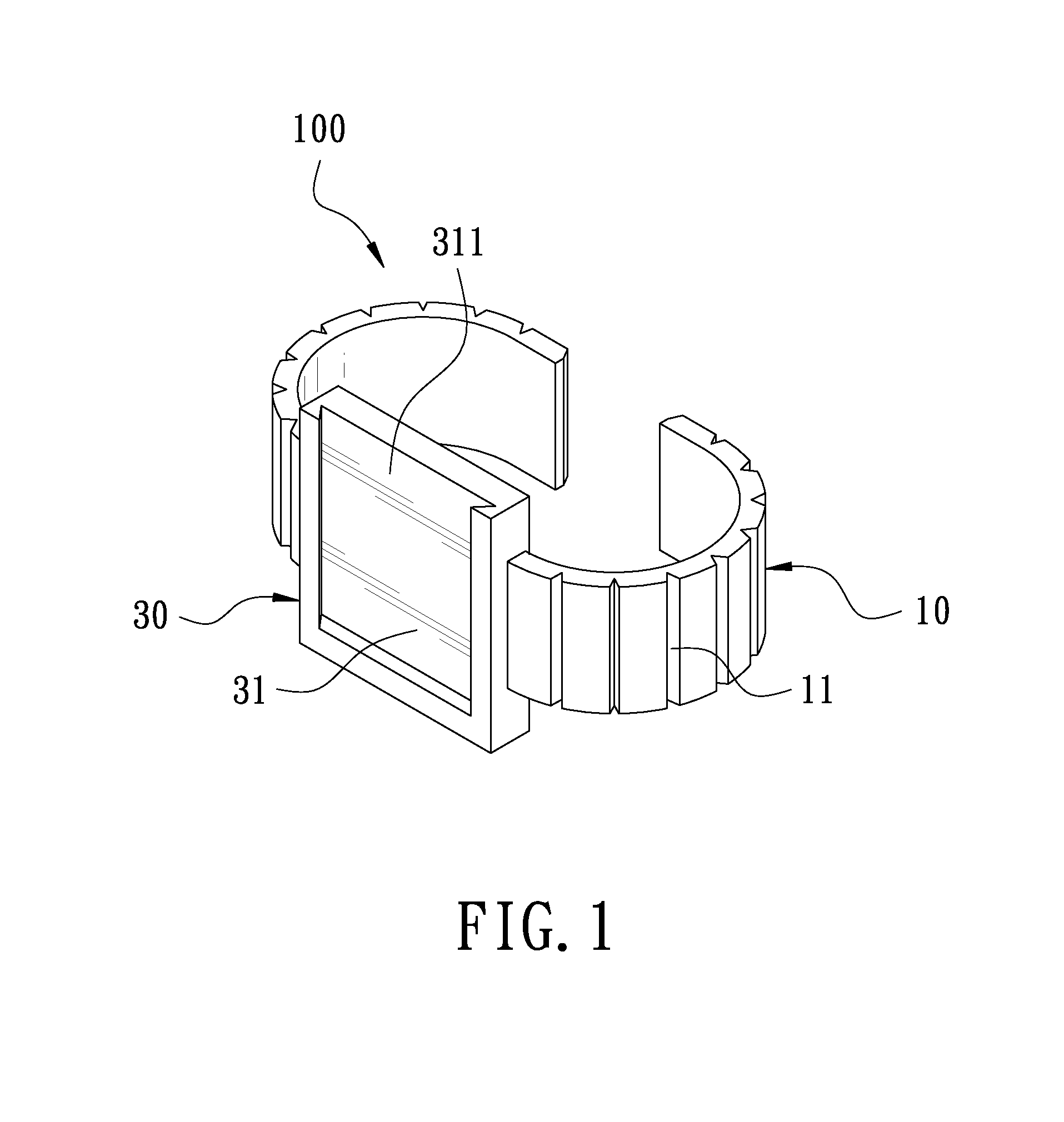
[0015]FIG. 1 is a perspective view of the present invention. FIG. 2 is a sectional view of the present invention. The present invention discloses a wireless charge and discharge wrist band 100 for placing a cell phone. The wireless charge and discharge wrist band 100 comprises a watch band 10, at least one battery 20, a watch seat 30, a main control board 40, a charge coil 50, a separator 60, a power supply coil 70, and a NFC (Near Field Communication) coil 80.

[0016]The watch band 10 is made of a waterproof material, which has the resistance of water. The watch band 10 has a plurality of spaced V-shaped grooves 11 along a short axis thereof. The V-shaped grooves 11 are arranged along the short axis of the watch band 10 to traverse the watch band 10. Through the V-shaped grooves 11, the watch band 10 forms a multi-section crawler structure. Through the...


PUM


Abstract

A wireless charge and discharge wrist band for placing a cell phone includes a watch band. The watch band is embedded with a plurality of batteries. The watch band has V-shaped grooves between the batteries. The watch band is provided with a watch seat. The watch seat has an engaging trough thereon. The bottom of the watch seat is provided with a charge coil, and the top of the watch seat is provided with a power supply coil. The charge coil and the power supply coil are connected with the batteries. The engaging trough is adapted for engagement of the cell phone. Through electromagnetic induction to transmit power, the cell phone can be charged anytime. During charging, the cell phone can be used and taken along. The watch band can be in different colors to mate with cell phone to enhance its fashion.

Description

BACKGROUND OF THE INVENTION[0001]1. Field of the Invention[0002]The present invention relates to a wireless charge and discharge device, and more particularly to a wireless charge and discharge wrist band for placing a cell phone.[0003]2. Description of the Prior Art[0004]A cell phone is a common portable communication apparatus. Along with the development of electronic technique, the functions of the cell phone are increasing day by day. The cell phone becomes an essential appliance in our modern life. However, the cell phone needs electricity when in use. The conventional cell phone proceeds with power transmission through a wired power supply device. By using the wired power supply device to proceed with power transmission for the cell phone, the range for the user to use the cell phone is limited to where the wired poser supply device is located. The cell phone cannot be charged anytime and anywhere. During using the cell phone, the cell phone may have a shortage of power. When ...

Claims


Application Information

Patent Timeline
IPC IPC(8): H04B5/00H04M1/725H02J50/10
CPCH04M1/725H04B5/0037A44C5/0007H02J7/0044H02J50/10H04M1/0254H04M1/04H04B5/26H04B5/79
Inventor WANG, ROBERTYEH, SHIH-MING
Owner COREMATE TECH CO LTD
Learn More