
Patient interface identification system

a patient interface and identification system technology, applied in the field of patient interface identification system, can solve the problems of obstructing breathing during sleep, unpleasant and painful red marks on the patient's face, unwanted air leakage, etc., and achieve the effect of less time-consuming and easier application for users

Active Publication Date: 2015-07-09
KONINKLJIJKE PHILIPS NV
View PDF6 Cites 31 Cited by
  • Summary
  • Abstract
  • Description
  • Claims
  • Application Information

AI Technical Summary

Benefits of technology

The present invention provides an improved system for identifying the best patient interface for a user by analyzing their facial features. The new system is easier to use, more practical, and can provide information about the size, shape, or type of patient interface recommended for the user. This helps the user to select the most suitable interface for their face. The system uses a least square method to calculate the similarity between different pictures and identify the reference picture with the closest resemblance to the user's facial features. This improves the picture comparison and eases the identification of the reference picture. Overall, this invention offers a better solution for identifying the best patient interface for users.

Problems solved by technology

The human airway is composed of walls of soft tissue which can collapse and thereby obstruct breathing during sleep.
An incorrect fit of the patient interface may not only lead to unwanted air leaks at the mask-to-face interface, but may also cause excessive pressure points on the skin of the patient's face that again may cause unpleasant and painful red marks in the patient's face.
This is, of course, bothersome and time-consuming for the user.
In many practical appliances the facial dimensions cannot be measured manually (since there is no time) or no absolute dimensions of the user's face are known in advance, so that the device and method proposed in US 2006 / 0235877 A1 is not only disadvantageous, but can also not be applied in many practical situations.

Method used


Image

  • Patient interface identification system
  • Patient interface identification system
  • Patient interface identification system

Examples


Embodiment Construction

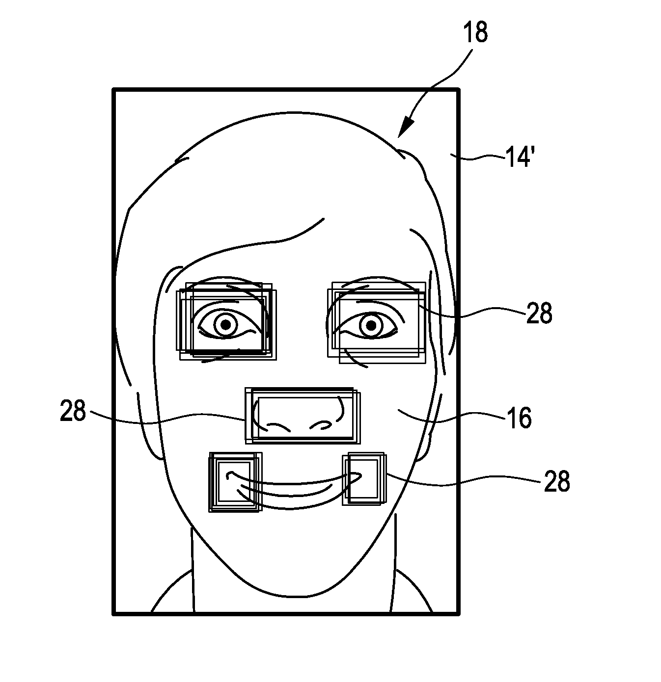
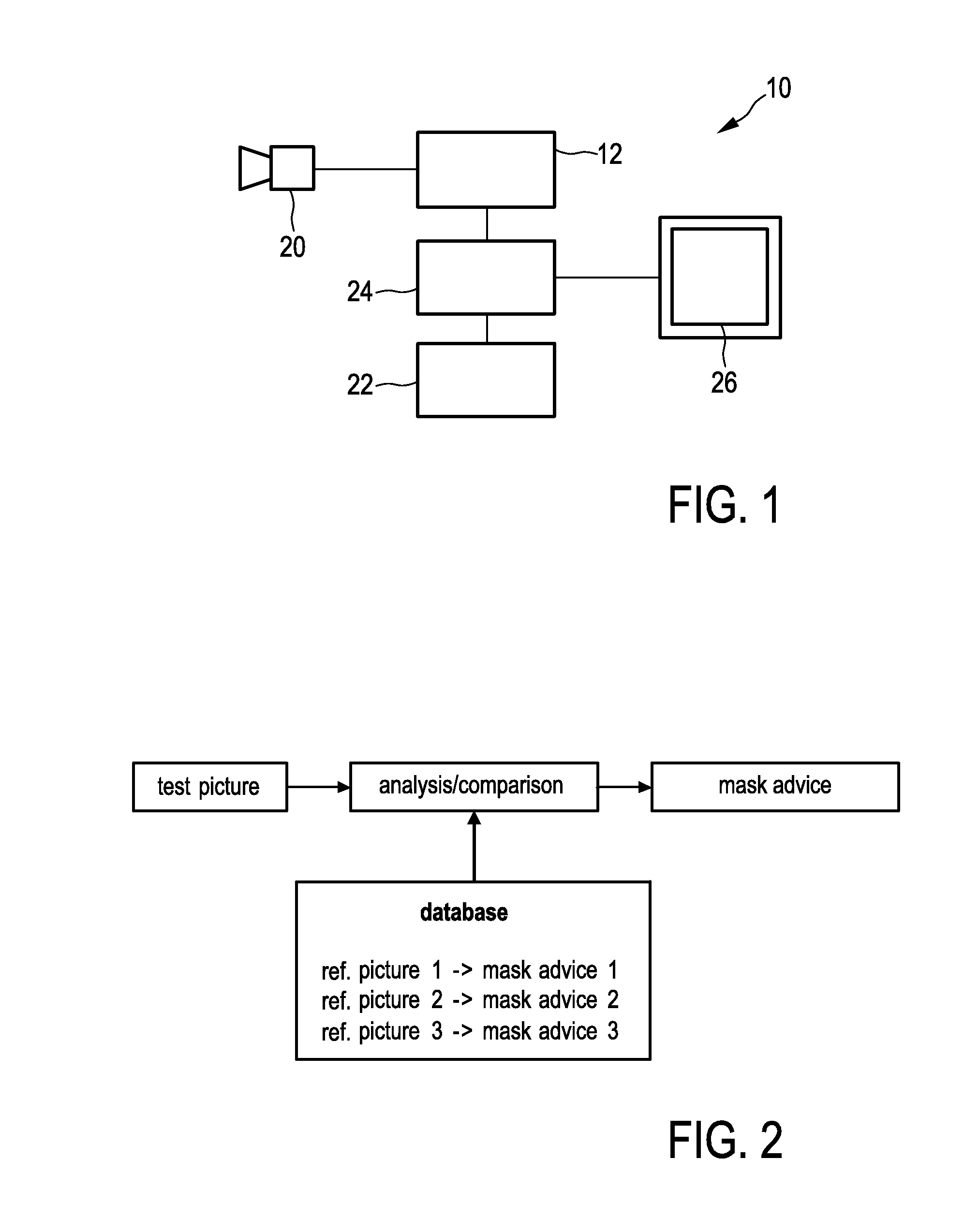
[0064]FIG. 1 shows an embodiment of a patient interface identification system for identifying a patient interface that is suited for a face of a user, which system may also be referred to as a mask fitting system. The proposed system is therein in its entirety denoted with reference numeral 10. According to the illustrated embodiment, the patient interface identification system 10 comprises a receiving unit 12 for receiving a test picture 14 (see e.g. FIG. 4), which test picture 14 includes a face 16 of a user 18. The receiving unit 12 may, for example, be realized as a connection interface that is suitable for receiving or downloading pictures to the system 10. Examples may be a USB-interface, firewire interface, a Bluetooth interface, a wireless LAN interface or an infrared interface. However, the receiving unit may also be a simple interface that is connected to the Internet for downloading the test picture 14 from any external database. Even further, the receiving unit 12 may be...


PUM


Abstract

The present invention relates to a patient interface identification system for identifying a patient interface that is suited for a face (16) of a user (18), comprising: a receiving unit (12) for receiving a test picture (14) including the face (16) of the user (18); a database (22) for storing reference picture including faces of other users, wherein each reference picture is referenced to a patient interface advice; a processing unit (24) for comparing the received test picture (14) with at least a subset of said reference pictures stored in the database (22), wherein comparing said test picture (14) with said subset of reference pictures includes a comparison of image based features of the user's face (16) and the other users' faces; and a user interface (26) for communicating a patient interface advice including information related to a patient interface that is suited for the face (16) of the user (18), which patient interface advice is based on the comparison of said test picture (14) with the subset of reference pictures stored in the database (22).

Description

FIELD OF THE INVENTION[0001]The present invention relates to a patient interface identification system for identifying a patient interface that is suited for a face of a user. In a further aspect, the present invention relates to a corresponding method for identifying a patient interface that is suited for a face of a user. In a still further aspect, the present invention relates to a corresponding method of controlling said patient interface identification system. Still further, the present invention relates to a corresponding computer program comprising program code means for causing a computer to carry out the steps of said method when said computer program is carried out on a computer.BACKGROUND OF THE INVENTION[0002]Patient interfaces, such as masks in pressure support systems, are used for delivering gas to a user. Such gases like air, cleaned air, oxygen, or any modification thereof are submitted to the user (also refer to as patient) via the patient interface in a pressurize...

Claims


Application Information

Patent Timeline
IPC IPC(8): G06K9/00A61M16/06G06K9/62
CPCG06K9/00261G06K9/00281A61M16/06G06K9/6215G06K9/00248A61M16/0051A61M2016/0661A61M2205/502A61M2205/52G06V40/16A61M16/021G06V40/167G06V40/165G06V40/171G06F18/22
Inventor HO, PETER CHI FAIZNAMENSKIY, DMITRY NIKOLAYEVICHSOFRANKO, RICHARD ANDREW
Owner KONINKLJIJKE PHILIPS NV
Learn More