Vehicle control system

Inactive Publication Date: 2015-07-09
TOYOTA JIDOSHA KK
View PDF0 Cites 41 Cited by
  • Summary
  • Abstract
  • Description
  • Claims
  • Application Information

AI Technical Summary

Benefits of technology

The present invention relates to a vehicle control system for coasting control, which is for reducing fuel consumption by disengaging the engine from the drive wheels while still using the engine for actual driving. The invention is designed to provide a comfortable and safe driving experience for the driver and passengers. The system reduces the number of intake and exhaust valves to be deactivated during braking, which increases the engine braking force to decelerate the vehicle. This allows for more efficient fuel consumption and proper deceleration for a smooth driving experience. Additionally, the system reduces the number of valves to be deactivated when the vehicle speed is increased during coasting control, which increases the pumping loss of the engine, resulting in more engine braking force. Overall, this invention provides a vehicle control system that improves fuel efficiency while still providing a comfortable driving experience for the driver and passengers.

Problems solved by technology

By contrast, in case of carrying out the coasting control without stopping the engine, the fuel economy will not be improved as the case of stopping the engine.

Method used


Image

  • Vehicle control system
  • Vehicle control system
  • Vehicle control system

Examples


Embodiment Construction

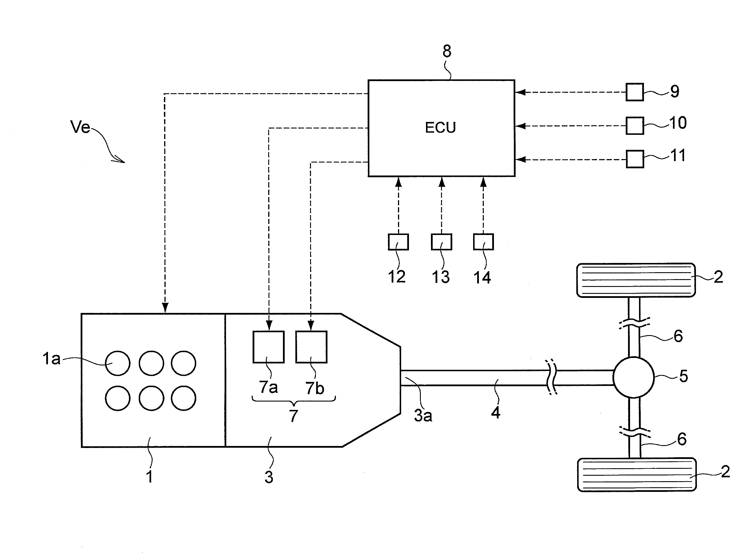
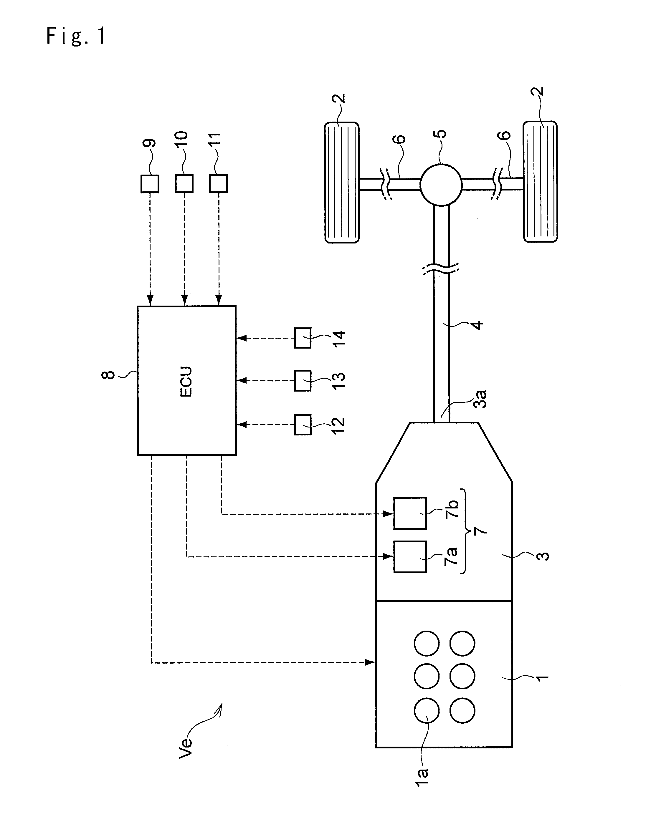
[0024]Next, the present invention will be explained in more detail with reference to the accompanying drawings. FIG. 1 shows a drive line and a control line of the vehicle to which the control system of the present invention is applied. As shown in FIG. 1, the vehicle Ve is comprised of an engine 1, and an automatic transmission 3 connected to an output side of the engine 1 to transmit a power of the engine 1 to drive wheels 2. Specifically, the automatic transmission 3 is disposed on the output side of the engine 1, and an output shaft 3a of the automatic transmission 3 is connected to the drive wheels 2 to transmit power therebetween through a propeller shaft 4, a differential gear 5 and a drive shaft 6. Thus, FIG. 1 shows an example of rear-drive layout of the vehicle Ve in which the engine 1 is connected to the rear drive wheels 2 through the propeller shaft 4. However, the control system of the present invention may also be applied to a front drive vehicle and a four-wheel driv...


PUM


Abstract

A vehicle control system is provided. The vehicle control system is applied to a vehicle comprising an engine having a plurality of cylinders, a power transmission route between the engine and drive wheels and a clutch device adapted to selectively connect and disconnect the power transmission route, and that is configured to disconnect the power transmission route during running to allow the vehicle to coast. The vehicle control system is comprised of: a means that detects a vehicle speed; a means detecting an operation of an accelerator by a driver; a means detecting a speed of the engine; an execution means executing a coasting control when an operating amount of an accelerator is reduced to be smaller than a predetermined value during running, by bringing the clutch device into disengagement to disconnect the power transmission route while controlling the engine in a manner such that the engine speed is reduced to be lower than an idling speed that is lower than the engine speed of a case in which the coasting control is not carried out; and a deactivation means connecting the power transmission route by bringing the clutch device into engagement while stopping fuel supply to the engine and deactivating intake valves and exhaust valves of the cylinders, when the vehicle speed exceeds a reference speed or an increasing amount of the vehicle speed exceeds a reference value.

Description

TECHNICAL FIELD[0001]The present invention relates to a control system for a vehicle that is provided with a clutch for selectively connect and disconnect a prime mover to / from drive wheels through a power transmission route, and that is allowed to coast by bringing the clutch into disengagement.BACKGROUND ART[0002]In order to improve fuel economy, a fuel cut-off control for stopping fuel supply to an engine during running, and a coasting control for coasting the vehicle by disconnecting the engine from a drive line during running have been in recent years. Specifically, the fuel cut-off is carried out to stop fuel supply to the engine given that an accelerator is returned to close an accelerator valve completely, and that an engine speed is higher than an idling speed so that a vehicle speed is higher than a predetermined speed. Under the fuel cut-off control, although the combustion of fuel in the engine is stopped, the engine is still rotating by a torque from the drive wheels. T...

Claims


Application Information

Patent Timeline
IPC IPC(8): B60W30/14B60W10/06B60W20/00B60W10/02
CPCB60W30/143B60W20/00B60W10/06B60W10/02B60W30/18072F02D41/0002F02D41/08F02D41/123F02N11/0833F16D48/02F16D2500/5085F16D2500/50227F16D2500/10412F16D2500/3144F16D2500/3108F16D2500/3067F02D41/022F02D2200/602F02D2200/501F02D2200/101F02D2041/0012F02D2041/001B60W2030/1809B60W2540/10B60W2510/0638B60W2520/10Y02T10/40F02D13/06F02D29/02F16D48/062F16D2500/30401F16D2500/3166F16D2500/5043F16D2500/5045F16D2500/7041Y02T10/12Y02T10/60
Inventor MITSUYASU, MASAKI
Owner TOYOTA JIDOSHA KK
Why Eureka
Try Eureka