Two-stroke engine with fuel injection

Active Publication Date: 2015-07-02
HONDA MOTOR CO LTD
View PDF2 Cites 0 Cited by
  • Summary
  • Abstract
  • Description
  • Claims
  • Application Information

AI Technical Summary

Benefits of technology

The present invention is aimed at providing a two-stroke engine with efficient cooling for the piston. The design allows for fuel injection without obstacles from the crankshaft, resulting in efficient delivery of fuel to the desired parts. The fuel injection device enhances heat removal from the piston and cylinder wall through evaporation of the fuel, allowing for efficient delivery of fuel to the back side of the piston and inner circumferential surface of the cylinder wall.

Problems solved by technology

However, because the lubricating oil supplied in this manner is highly limited in quantity, as compared to the case of a four-stroke engine equipped with a lubricating oil recirculation system, cooling of the piston and the cylinder is a major problem in the two-stroke engine.
However, according to the invention disclosed in JP04-237815A, in addition to a pump, special passages are required in the engine so that the complexity and the size of the engine inevitably increase.

Method used


Image

  • Two-stroke engine with fuel injection
  • Two-stroke engine with fuel injection
  • Two-stroke engine with fuel injection

Examples


first embodiment

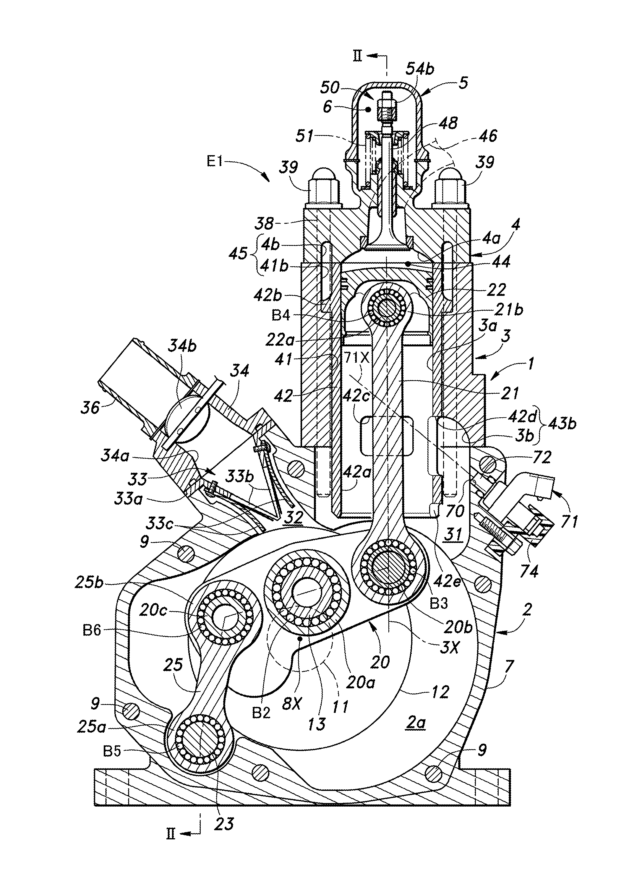
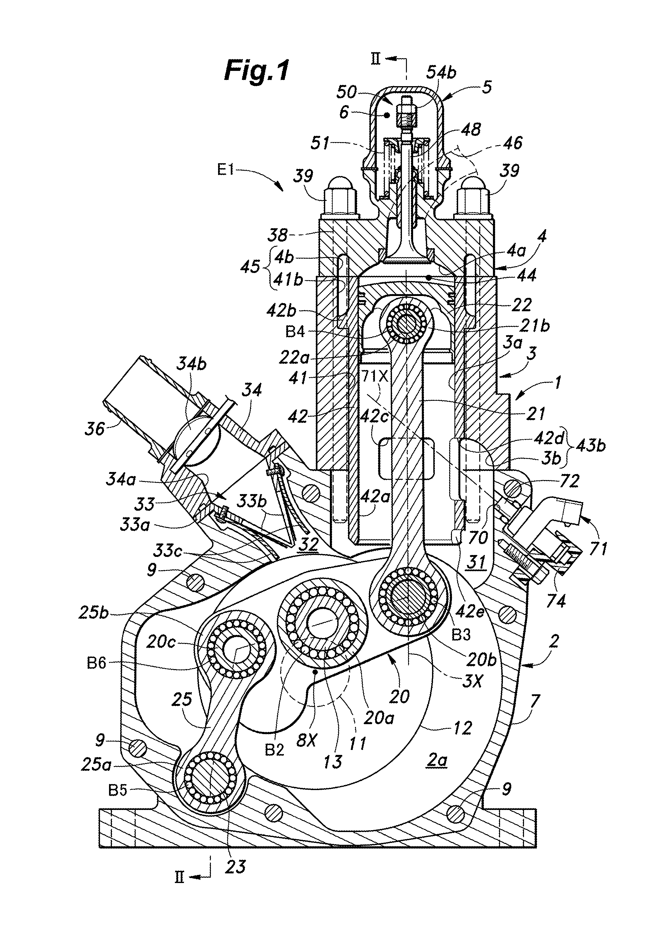
[0024]the present invention consisting of a uni-flow type, single cylinder, two-stroke engine (engine E1) is described in the following with reference to FIGS. 1 to 5.

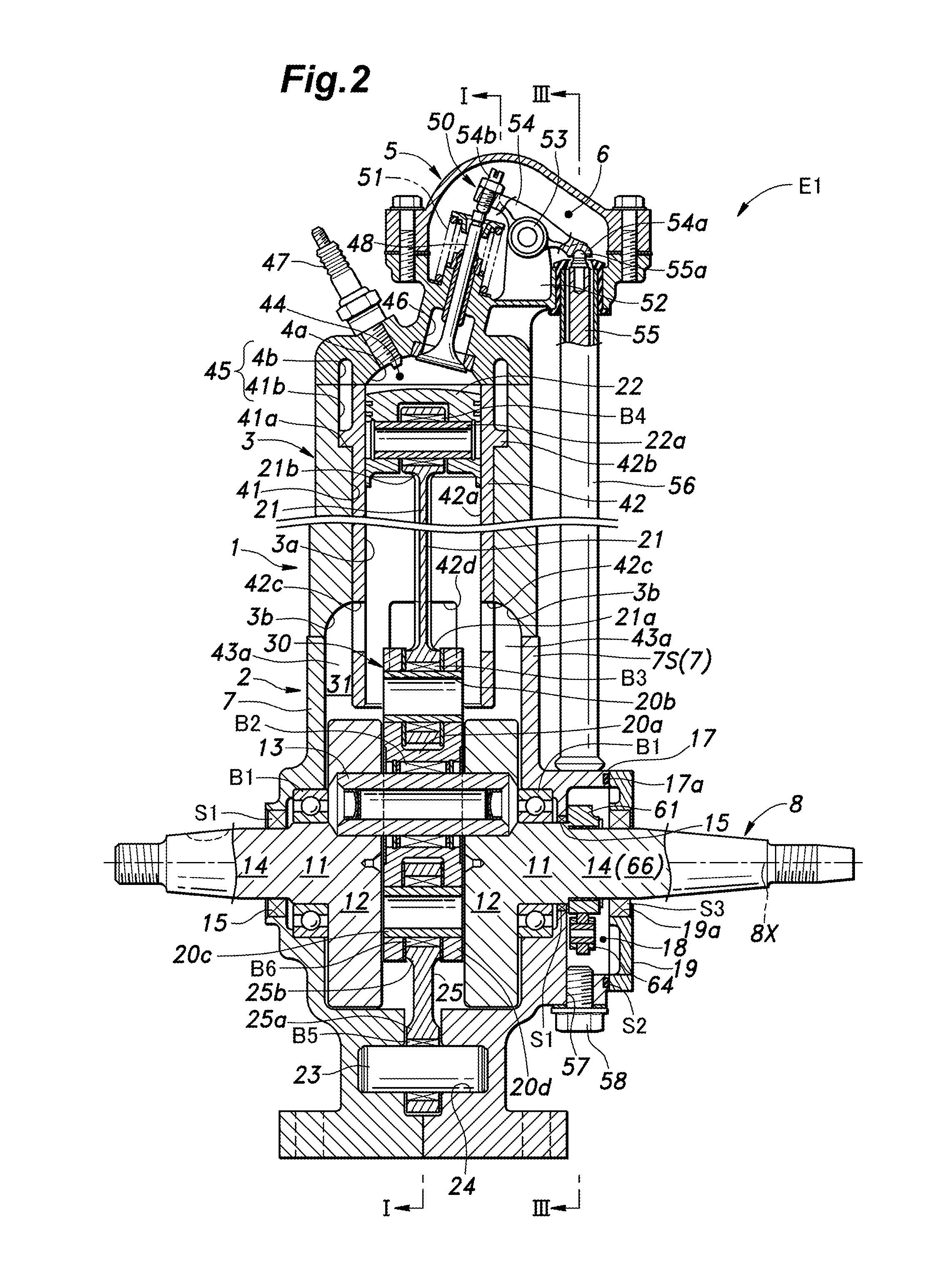
[0025]Referring to FIGS. 1 and 2, an engine main body 1 of the engine E1 is provided with a crankcase 2 defining a crank chamber 2a therein, a cylinder block 3 connected to the upper end of the crankcase 2 and defining a cylinder bore 3a therein, a cylinder head 4 connected to the upper end of the cylinder block 3 and a head cover 5 attached to the upper end of the cylinder head 4 to define an upper valve chamber 6 in cooperation with the cylinder head 4.

[0026]As best shown in FIG. 2, the crankcase 2 consists of two crankcase halves 7 having a parting plane extending perpendicularly to the crankshaft axial line 8X and joined to each other by seven threaded bolts 9 (FIGS. 1 and 3). Each crankcase half 7 includes a side wall 7S which is provided with an opening through which the corresponding end of a crankshaft 8 projec...

second embodiment

[0082]FIG. 7 shows the timing of fuel injection by the fuel injection device 71 with respect to the position of the piston 22 (or the crank angle) in the engine E2 of the

[0083]In the engine E2 of the second embodiment, the fuel injection device 71 injects fuel onto the piston 22 and the cylinder sleeve 42 via the lower open end of the cylinder sleeve 42 which is always in communication with the crank chamber 2a, and is shut off from the combustion chamber 44 by the piston 22. Therefore, the fuel injection device 71 may inject fuel at any timing. When the fuel is injected while the piston 22 is near the bottom dead center (region indicated by the solid arrow in FIG. 7), because the back side of the piston 22 is located on the fuel injection axial line 71X of the fuel injection device 71, the fuel may be injected upon the back side of the piston 22. The range over which fuel may be injected upon the back side of the piston 22 by the fuel injection device 71 may defined as the range ov...


PUM


Abstract

In a two-stroke engine including a scavenging port (43b) having an open end (42d) opening out in a side wall of the cylinder bore (3a) and communicating with a crank chamber (2a), the open end being configured to be closed and opened by the piston (22), a fuel injection device (71) is mounted on the engine main body so as to inject fuel onto a back side of the piston and / or a part of the side wall of the cylinder bore located under the piston via the open end of the scavenging port or via the open lower end of the cylinder bore. The fuel deposited on the surfaces of the piston and the cylinder inner wall promotes the cooling of such parts.

Description

TECHNICAL FIELD[0001]The present invention relates to a two-stroke engine, and in particular to a two-stroke engine with fuel injection.BACKGROUND OF THE INVENTION[0002]The two-stroke engine is often preferred over the four-stroke engine in the field of general purpose engines because of the simplicity in the structure. The two-stroke engine is often not provided with any lubrication system, and the required lubrication is achieved by the use of mixed fuel containing lubricating oil. As the fuel is supplied to the crank chamber before being forwarded to the combustion chamber, the various rotating parts and sliding surfaces are lubricated. The lubricating oil is also known to be useful in removing heat from various moving parts. However, because the lubricating oil supplied in this manner is highly limited in quantity, as compared to the case of a four-stroke engine equipped with a lubricating oil recirculation system, cooling of the piston and the cylinder is a major problem in the...

Claims


Application Information

Patent Timeline
IPC IPC(8): F01P3/08F02M61/14F02B33/44F02B75/02F02B33/04
CPCF01P3/08F02B75/02F02B33/04F02B2075/025F02M61/14F01P2003/005F02B33/44F02B41/00F02M69/042F02B25/04F02D15/02F02M26/01F02F3/22F01M1/08F05C2201/021F02B3/06
Inventor YAMADA, YOSHIKAZUKURATA, MASHU
Owner HONDA MOTOR CO LTD
Why Eureka
Try Eureka