
Electronic cigarette

a technology of electronic cigarettes and cigarette shells, which is applied in the field of electronic cigarettes, can solve the problems of smoking smokers' mouth being burnt or scalded, the temperature of the mouthpiece is continuously increasing, and the safety hazards of smoking smokers, so as to reduce or avoid smoking tobacco-liquid by smokers

Inactive Publication Date: 2015-07-02
KIMREE HI TECH
View PDF1 Cites 77 Cited by
  • Summary
  • Abstract
  • Description
  • Claims
  • Application Information

AI Technical Summary

Benefits of technology

The present invention is an electronic cigarette that reduces or avoids the inhaling of tobacco-liquid by smokers. The technical effects of the invention include a vent column inside the mouthpiece vice cover and a cooling cavity between the mouthpiece main cover and the mouthpiece vice cover, which naturally cools and condenses fine tobacco-liquid particles on the inner wall. The heat exchanged between the smoke and the mouthpiece component is absorbed by the mouthpiece covers, which prevents burning or scalding the mouth of the smoker. The invention also includes a closed space for storing the tobacco-liquid, which makes the assembly and disassembly of the electronic cigarette convenient and quick.

Problems solved by technology

Moreover, due to the relatively thin wall thickness or the single-wall design of the inner wall of the mouthpiece cover, hot smoke will transfer heat with the mouthpiece cover when flowing through the mouthpiece cover, which leads to a continuous increasing of the mouthpiece temperature, exhibits a potential safety hazard of the smoker mouth being burnt or scalded.
In addition, because the tobacco-liquid cup is provided with components such as a cup seat and an atomizer seat etc. inside, this complex inner structure results in time-consuming and inconvenient during assembly and disassembly.

Method used


Image

  • Electronic cigarette
  • Electronic cigarette
  • Electronic cigarette

Examples


first embodiment

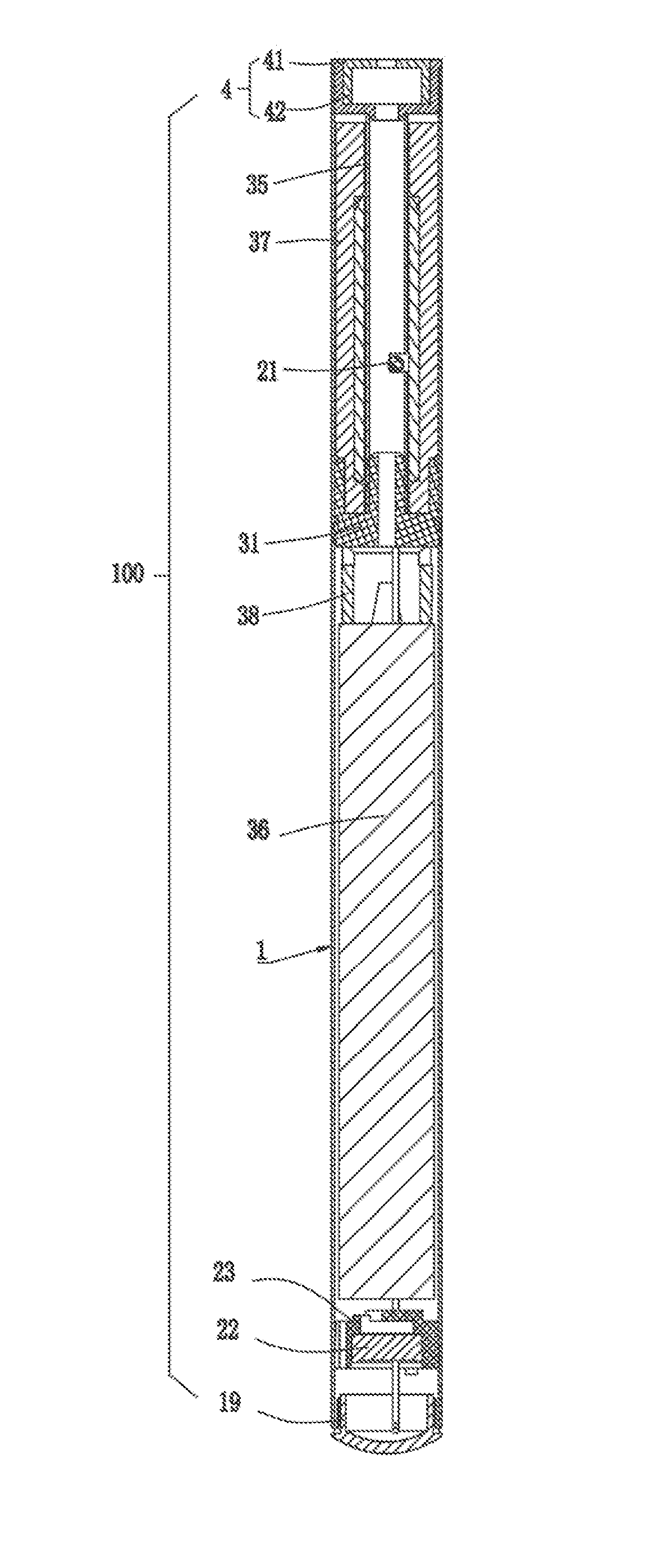
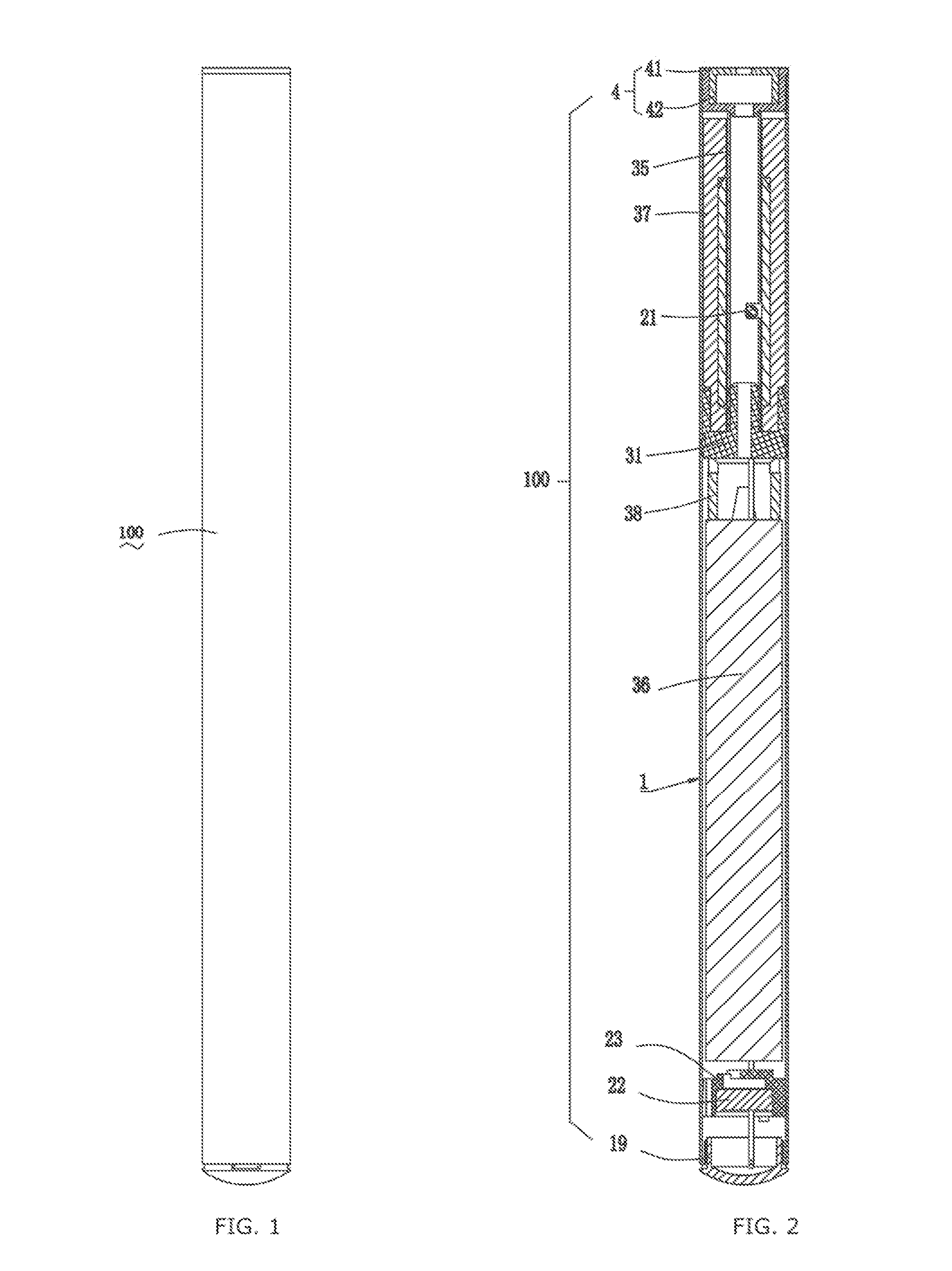
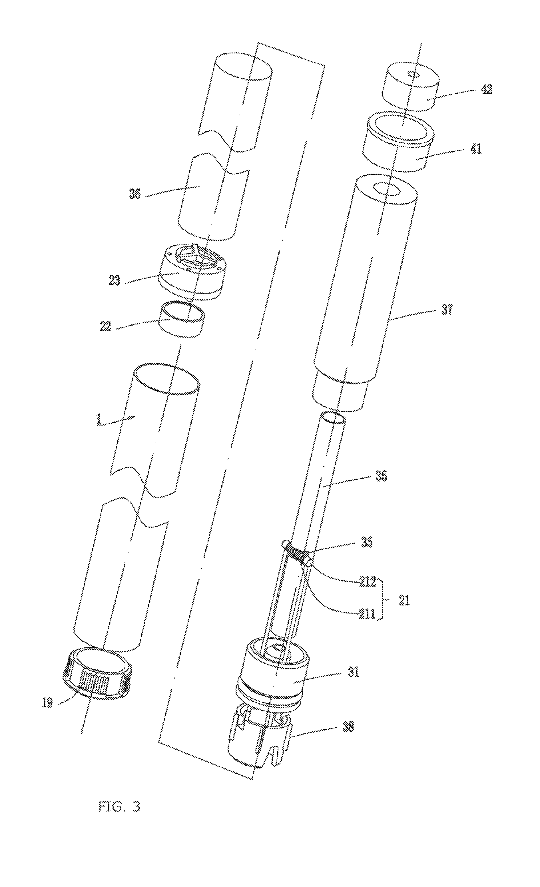
[0035]As shown in FIGS. 1 to 6, the present invention provides an electronic cigarette 100, which is an integrated electronic cigarette including a casing 1, the casing 1 is an integrated casing and shaped as a hollow cylinder. One end of the casing 1 is provided with a mouthpiece component 4 for sucking by smoker, and the other end of the casing 1 is closed by a base cover 19 on which an intake hole and an indicator light (not marked in the Fig.) are provided. Material of the casing 1 employs any one of following materials with the required hardness: metals, plastics, wood or paper materials.

[0036]The electronic cigarette 100 also includes: an atomizer 21 for transferring the tobacco-liquid into smoke by atomizing, a duct 35 for smoke flowing therethrough, a liquid-storage member 37 for storing tobacco-liquid, a liquid isolating member 31 for preventing tobacco-liquid from leaking, a storage power source 36 as well as a separate member 38 disposed between the liquid isolating membe...

second embodiment

[0045]As shown in FIGS. 7 to 10, the present invention provides an electronic cigarette 100′, which has a substantially same internal structure with that of the electronic cigarette 100, except for that the electronic cigarette 100′ includes a mouthpiece cover component 4′ similar to the mouthpiece cover component 4, wherein the mouthpiece cover component 4′ includes the mouthpiece main cover 41 and a mouthpiece vice cover 42′ used in combination with the mouthpiece main cover 41, and the mouthpiece vice cover 42′ is inserted into the main cover cooling cavity 413 of the mouthpiece main cover 41 and tensionally fixed to the side wall of the main cover cooling cavity 413. The mouthpiece vice cover 42′ includes a vice cover body 420′ formed by combination of a top wall and a side wall and comprising a vice cover cooling cavity 422′, a vent hole 421′ is provided on the top wall of the vice cover body 420′ and axially perforates to allow for venting between the inside and outside of the...

third embodiment

[0047]As shown in FIGS. 11 to 14, the present invention provides an electronic cigarette 100″, which has a substantially same internal structure with that of the electronic cigarette 100, except for that the electronic cigarette 100″ includes a mouthpiece cover component 4″ similar to the mouthpiece cover component 4, wherein the mouthpiece cover component 4″ also includes a mouthpiece main cover 41″ and a mouthpiece vice cover 42″ used in combination with the mouthpiece main cover 41″, the mouthpiece main cover 41″ is inserted into the casing 1 and fixed to the inner wall of the casing 1 by the tensional engagement of the outer side wall thereof. The mouthpiece main cover 41″ includes a main cover body 410″ tensionally engaging with the inner side wall of the casing 1, the bottom of the main cover body 410″ axially extends outward to form an insertion peg 411″ for inserting with the duct 35 in order to define one end of the duct 35, a vent hole 412″ is provided in the middle of the...


PUM


Abstract

Disclosed is an electronic cigarette (200), comprising a cylindrical housing (1) and an atomizer (21) provided inside the housing (1). An end of the housing (1) is provided with a suction nozzle primary cover (51) and a suction nozzle secondary cover (52), the suction nozzle primary cover (51) and the suction nozzle secondary cover (52) are successively inserted and fixed to an inner wall of the housing (1), and a cooling cavity is formed between the suction nozzle primary cover (51) and the suction nozzle secondary cover (52). Both the suction nozzle primary cover (51) and the suction nozzle secondary cover (52) are provided with a ventilation hole (512, 523) in communication with the cooling cavity, and a ventilation column (521) is formed in the suction nozzle secondary cover (52) for communicating the cooling cavity with the outside of the electronic cigarette. This electronic cigarette can reduce or avoid the possibility of a smoker inhaling cigarette liquid, and improve the safety of use.

Description

FIELD OF THE INVENTION[0001]The present invention relates to the field of electronic cigarette.BACKGROUND OF THE INVENTION[0002]Existing electronic cigarette typically includes a cylindrical shaped casing, inside of the casing is equipped with a tobacco-liquid cup for holding tobacco-liquid, an atomizer for atomizing the tobacco-liquid to smoke, and a storage power source for supplying power for the atomizer. A part of the casing is provided with a mouthpiece cover for sucking by smokers, the number of the mouthpiece cover is only one and the thickness of the inner-wall thereof is relatively thin. Since smoke flows out of the electronic cigarette via the mouthpiece cover from the inner of the electronic cigarette, and the vent hole of the mouthpiece cover is commonly a linear vent hole, some fine particles of the tobacco-liquid included in the smoke will be sucked into the mouth of the smoker directly from the linear vent hole, thus a phenomenon that the smokers suck in tobacco-liqu...

Claims


Application Information

Patent Timeline
Patent Type & Authority Applications(United States)
IPC IPC(8): A24F47/00A24F7/00A24D3/04A24F40/10A24F40/485
CPCA24F47/008A24F7/00A24D3/043A24F40/10A24F40/485
Inventor LIU, QIUMING
Owner KIMREE HI TECH
Learn More