
Exterior member manufacturing method

Inactive Publication Date: 2015-06-25
YAZAKI CORP
View PDF3 Cites 5 Cited by
  • Summary
  • Abstract
  • Description
  • Claims
  • Application Information

AI Technical Summary

Benefits of technology

The present invention provides an exterior member, an electric wire wiring structure, and a method of manufacturing the exterior member with a high-visibility identifying mark that is easy to recognize, regardless of the material of the exterior member. The identifying mark can be colored on the outer surface of the exterior member body, and its visibility is ensured even if the exterior member body is bent or has a three-dimensional shape. The method of manufacturing the exterior member allows for efficient coloring or attachment of the identifying mark, as well as improved identifying property of the exterior member during vehicle maintenance.

Problems solved by technology

Firstly, as described in the JP-A-2003-168329, when the plurality of kinds of identifying marks which are different from each other in color and size are intermittently given in a longitudinal direction of the long exterior member, it is possible that the process of coloring the plurality of colors becomes complex, the coloring device is upsized, and manufacturing cost is increased.
In addition, when the electric wire is wired under the vehicle floor or the like, although the exterior member is bent to have a shape corresponding to the shape of the floor, the identifying mark moves to a position where the identifying mark is difficult to be visually recognized, for example, the floor side, because of the bending, and it may become hard to identify.
However, because an exterior member made of metal cannot be adopted, and it is necessary to change the manufacturing process according to the material of the exterior member, the process becomes inefficient.
In addition, when the whole outer surface of the metal exterior member is colored to have an identifying color, there is a problem which is that material cost is high because a large amount of color agent is used.

Method used


Image

  • Exterior member manufacturing method
  • Exterior member manufacturing method
  • Exterior member manufacturing method

Examples


Embodiment Construction

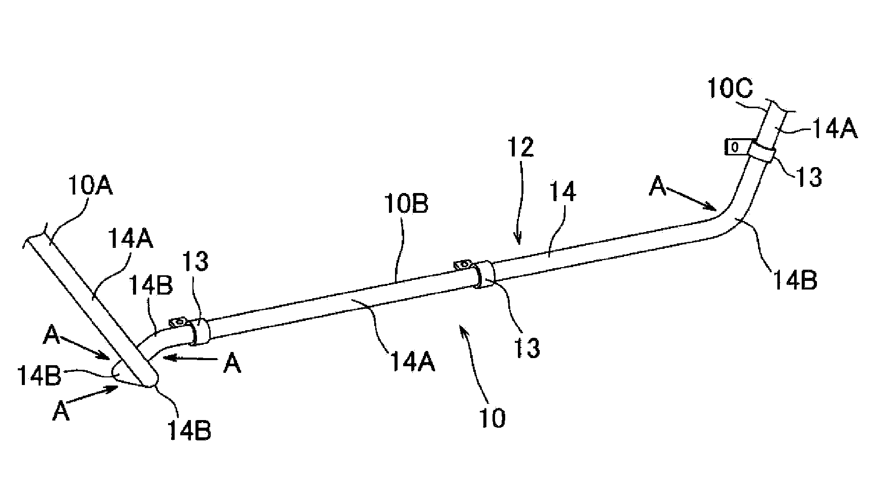
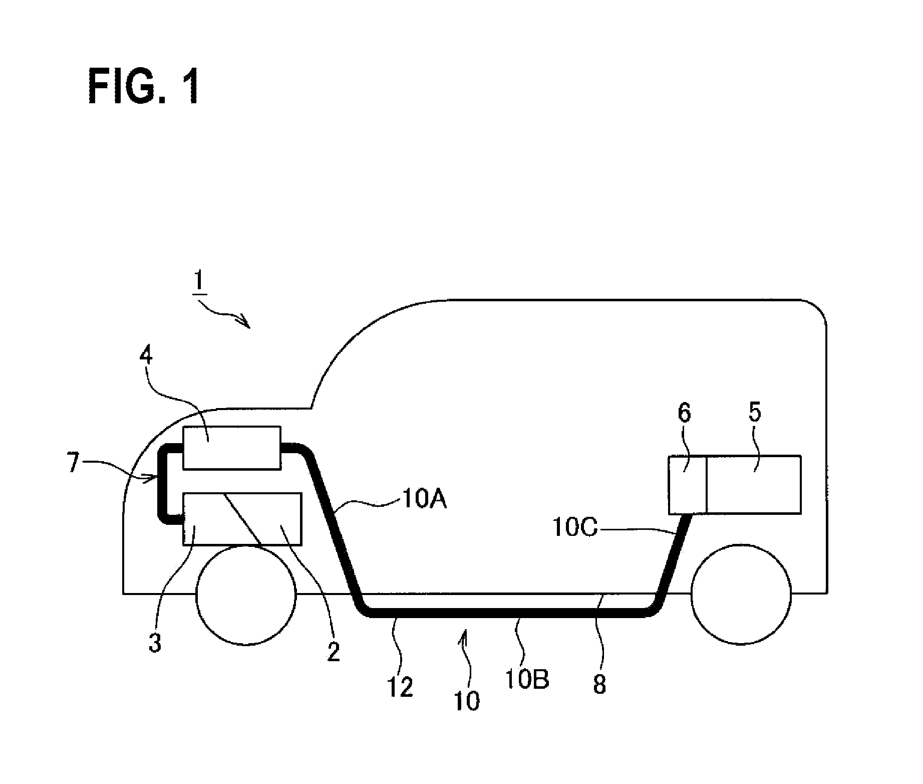
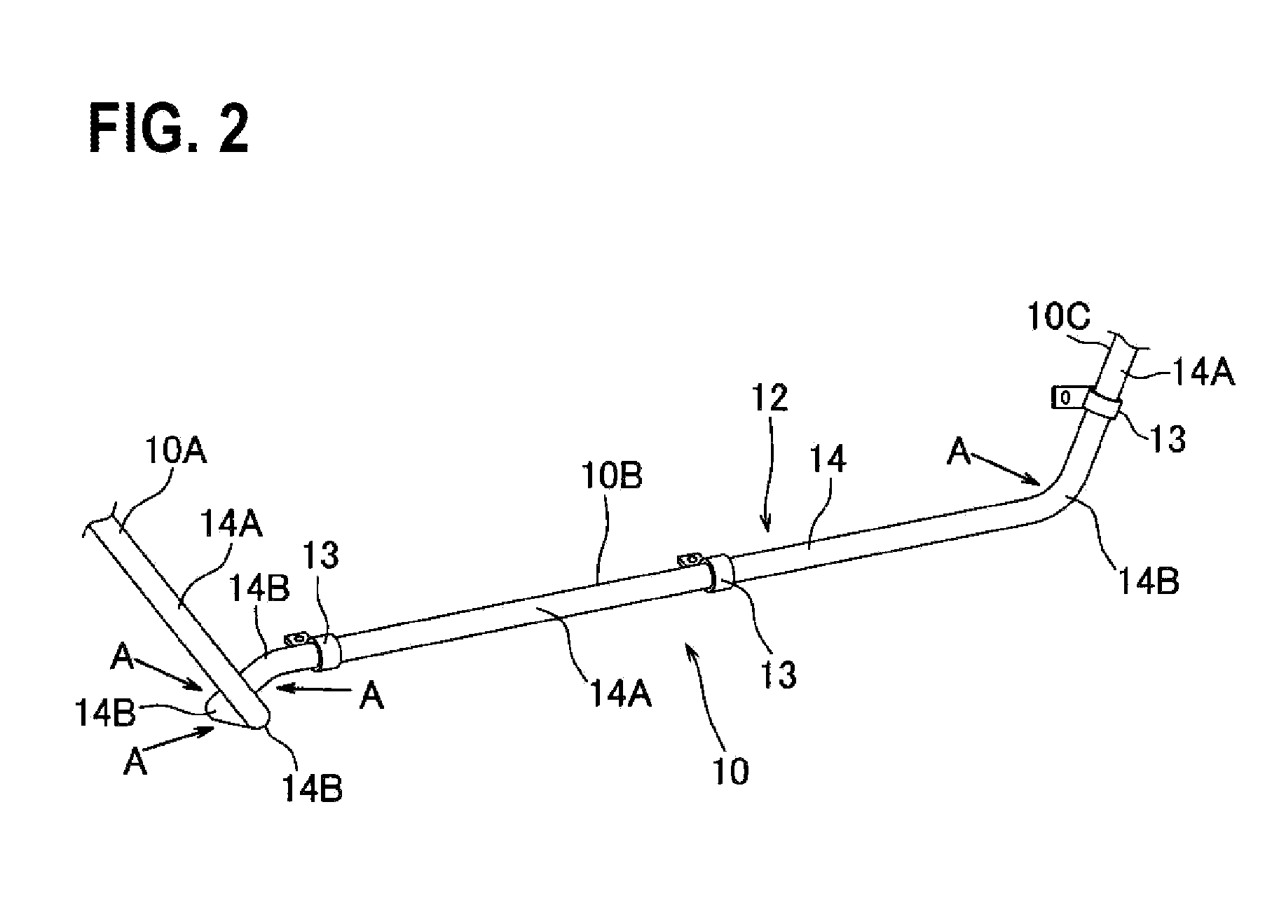
[0023]An electric wire wiring structure and an exterior member 20 which is used in the electric wire wiring structure according to an embodiment of the present invention are described by using FIGS. 1 to 4B. In the embodiment, an automobile (namely, vehicle) 1, especially a hybrid vehicle which is driven with the driving force of both an engine and an electric motor, is illustrated, and an electric wire wiring structure 10, which the automobile 1 is provided with, is described. In addition, the automobile 1 is not limited to a hybrid vehicle, but also may be an electric vehicle which is driven by the driving power from an electric motor.

[0024]The automobile 1 includes an engine 2 and an electric motor 3 which are loaded in the engine room at the front of the automobile, an inverter 4 which is provided near the electric motor 3, a battery 5 which is loaded below the trunk room or a seat at the rear of the automobile, and a junction block 6 which is electrically connected to the batte...


PUM

PropertyMeasurementUnit
Circumferenceaaaaaaaaaa

Abstract

A method of manufacturing an exterior member which covers the circumference of an electric wire, which is wired between electrical components, along the electric wire, and is supported by a supporting body while one side in a circumferential direction is exposed, the exterior member including an exterior member body that is formed into a long cylindrical shape and which has a predetermined background color and an identifying mark that is provided on the outer surface of the exterior member body and which has another predetermined color different from the background color, includes providing the identifying mark on the outer surface of the exterior member body having a straight shape and bending the exterior member body at a middle position in the longitudinal direction after the providing the identifying mark.

Description

CROSS REFERENCE TO RELATED APPLICATIONS[0001]This application is a continuation of PCT application No. PCT / JP2013 / 073443, which was filed on Aug. 30, 2013 based on Japanese Patent Application (No. 2012-192884) filed on Sep. 3, 2012, the contents of which are incorporated herein by reference.BACKGROUND OF THE INVENTION[0002]1. Field of the Invention[0003]The present invention relates to an exterior member, an electric wire wiring structure, and a method of manufacturing the exterior member, and more specifically, to an exterior member which covers the circumference of an electric wire along the electric wire which is wired between electrical components, an electric wire wiring structure which includes the exterior member, and a method of manufacturing the exterior member.[0004]2. Related Art[0005]In an automobile, various electrical components or electronic devices are loaded, and electric wires (in other words, wire harnesses) are wired in order to transmit electric power, control s...

Claims


Application Information

Patent Timeline
IPC IPC(8): H01B13/34H01B7/17H01B7/36
CPCH01B13/34H01B7/17H01B7/36H02G3/0481H02G2200/20Y10T29/49227B60R16/0215
Inventor INAO, SHINICHIADACHI, HIDEOMIOGUE, TAKESHIOGA, TATSUYASUGURO, MASAAKIOZAKI, YOSHIAKIYOSHIDA, HIROYUKI
Owner YAZAKI CORP
Learn More