Liquid crystal display device

a liquid crystal display and display device technology, applied in non-linear optics, instruments, optics, etc., can solve the problems of easy visual recognition of white defects, easy light leakage, and easy uneven luminance, and achieve the effect of reducing luminance unevenness

Inactive Publication Date: 2018-09-11
PANASONIC LIQUID CRYSTAL DISPLAY CO LTD +1
View PDF9 Cites 0 Cited by
  • Summary
  • Abstract
  • Description
  • Claims
  • Application Information

AI Technical Summary

Benefits of technology

[0004]The inventors have found that luminance unevenness occurs in a vicinity of a corner of a display screen in a lateral electric field type liquid crystal display device typified by an IPS (In-Place-Switching) type liquid crystal display device among liquid crystal display devices having the curved display surfaces. Specifically, in the case where the TFT substrate and the CF substrate are formed in a curved shape such that a rear surface side becomes convex, a tensile (extension) stress acts on a glass substrate constituting the TFT substrate while a compressive stress acts on a glass substrate constituting the CF substrate. A problem does not occur if curvatures of the two glass substrates are ideal (constant), but actually a deviation occurs with respect to the ideal (constant) curvature by reaction to bending. The occurrence of such deviation generates a phase difference between the glass substrates in a direction oblique to liquid crystal molecules. In the lateral electric field type, because the liquid crystal molecules are disposed substantially parallel to the TFT substrate and the CF substrate, oblique light (polarized light) further rotates by an influence of the phase difference. The rotation of the polarized light is not canceled by a polarizing plate, and light leakage occurs. As a result, a white defect is easily visually recognized when a black image is displayed. Because the light leakage easily occurs in the vicinity of the corner where the deviation from the ideal curvature increases, the luminance unevenness easily occurs in the vicinity of the corner of the display screen.
[0007]The present disclosure has been made in view of the above circumstances, and an object of the present disclosure is to reduce luminance unevenness occurring in a vicinity of a corner of a display screen in a lateral electric field type liquid crystal display device having a curved display surface.
[0016]Owing to the liquid crystal display device according to the present disclosure, a lateral electric field type liquid crystal display device with a curved display surface reducing luminance unevenness occurring in a vicinity of a corner of a display screen, can be obtained.

Problems solved by technology

The rotation of the polarized light is not canceled by a polarizing plate, and light leakage occurs.
As a result, a white defect is easily visually recognized when a black image is displayed.
Because the light leakage easily occurs in the vicinity of the corner where the deviation from the ideal curvature increases, the luminance unevenness easily occurs in the vicinity of the corner of the display screen.
Therefore, a distortion increases in the vicinity of the corner in the display panel, and the luminance unevenness is easily visually recognized.

Method used


Image

  • Liquid crystal display device
  • Liquid crystal display device
  • Liquid crystal display device

Examples


Embodiment Construction

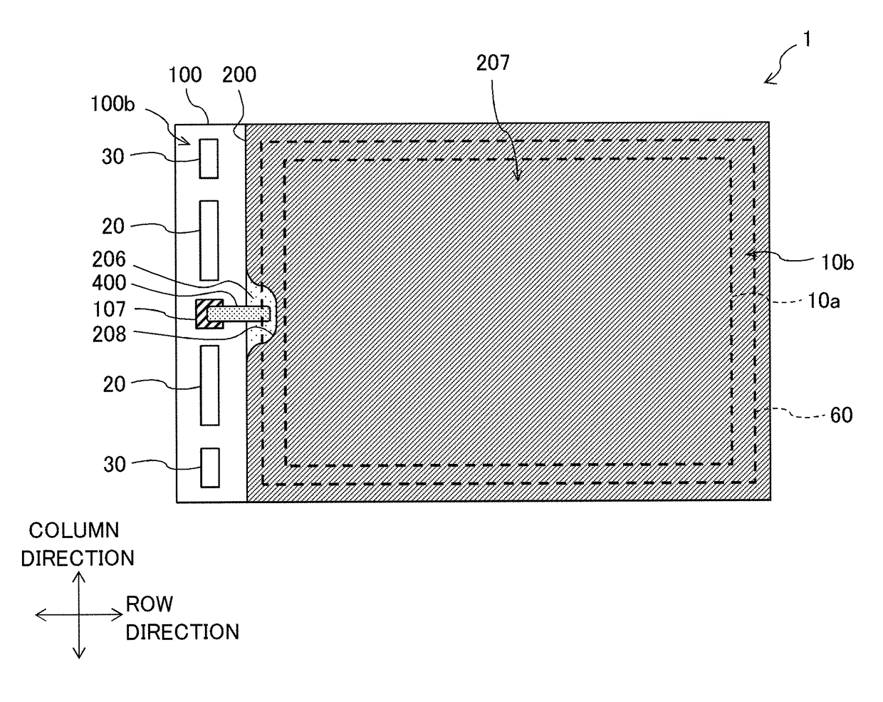
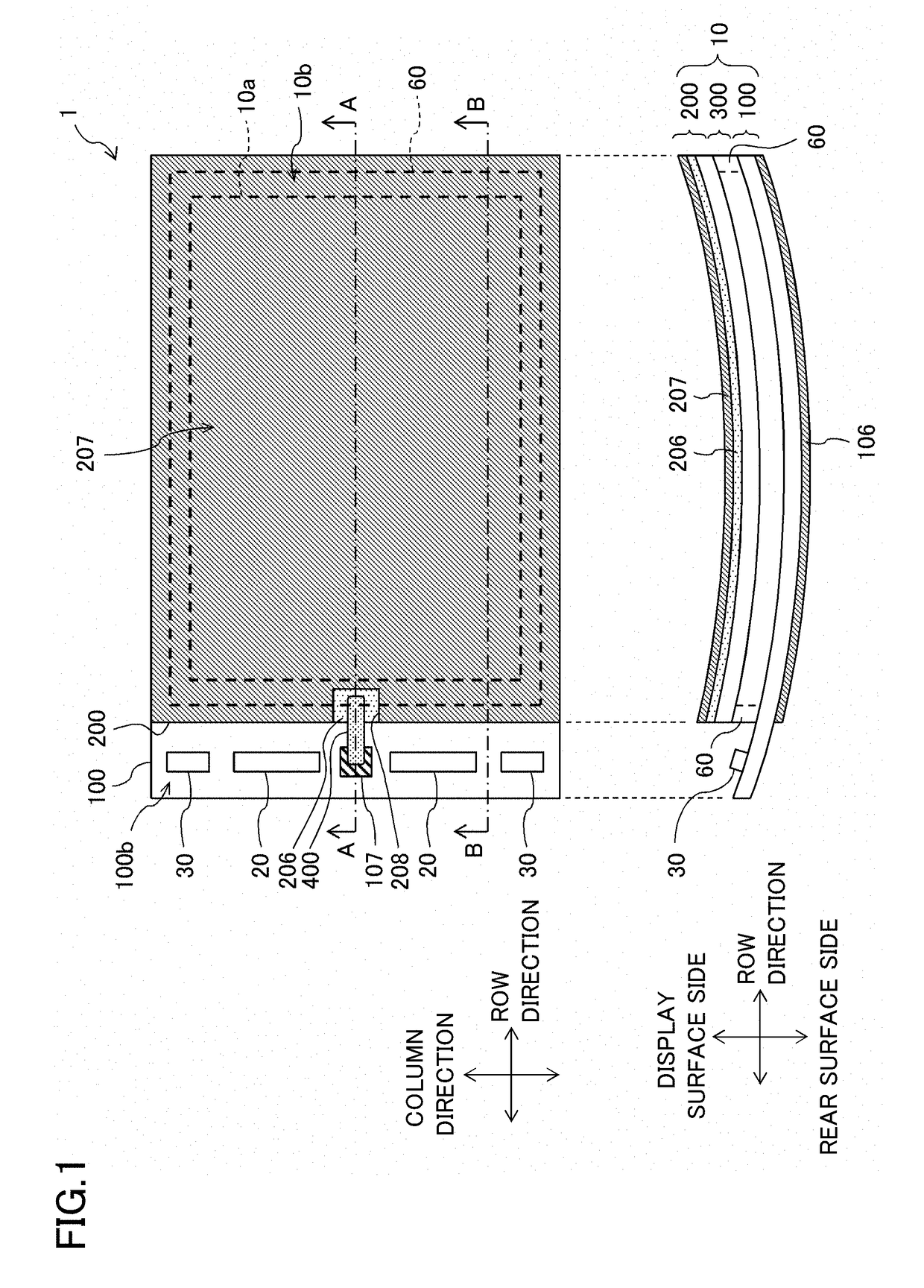
[0030]Hereinafter, an exemplary embodiment of the present disclosure will be described with reference to the drawings. FIG. 1 is a plan view and a side view illustrating a schematic configuration of liquid crystal display device 1 according to the exemplary embodiment. Liquid crystal display device 1 includes display panel 10, a driver (for example, source driver IC 20 and gate driver IC 30), a control circuit (not illustrated), and a backlight device (not illustrated). Display panel 10 includes thin film transistor substrate 100 (hereinafter, referred to as a TFT substrate) as a first substrate, color filter substrate 200 (hereinafter, referred to as a CF substrate) as a second substrate, and liquid crystal layer 300 disposed between TFT substrate 100 and CF substrate 200. TFT substrate 100 and CF substrate 200 are fixedly bonded together using sealing material 60 that is formed into a frame shape at a position corresponding to a peripheral portion of CF substrate 200. Liquid cryst...


PUM

PropertyMeasurementUnit
lateral electric fieldaaaaaaaaaa
luminanceaaaaaaaaaa
tensileaaaaaaaaaa

Abstract

A lateral electric field type liquid crystal display device having a curved display surface, comprises: a curved first substrate including a plurality of gate lines, a plurality of data lines, a pixel electrode, and a common electrode; a curved second substrate that is disposed opposite to the first substrate, the second substrate including a polarizing plate; a liquid crystal layer disposed therebetween; a sealing material bonding the first substrate and the second substrate together; and a driver that outputs a drive signal to at least the plurality of gate lines or the plurality of data lines. In the polarizing plate, at least a part of a side near the driver overlaps the sealing material or is disposed outside the sealing material in planar view.

Description

CROSS-REFERENCE TO RELATED APPLICATION[0001]This application claims priority from Japanese application JP 2016-108052, filed May 31, 2016. This Japanese application is incorporated herein by reference.TECHNICAL FIELD[0002]The present invention relates to a liquid crystal display device.BACKGROUND[0003]Recently there is proposed a liquid crystal display device having a curved display surface (for example, Unexamined Japanese Patent Publication No. 2009-92884). In such a liquid crystal display device, a pair of substrates (a thin film transistor substrate (TFT substrate) and a color filter substrate (CF substrate)) are formed so as to be curved.SUMMARY[0004]The inventors have found that luminance unevenness occurs in a vicinity of a corner of a display screen in a lateral electric field type liquid crystal display device typified by an IPS (In-Place-Switching) type liquid crystal display device among liquid crystal display devices having the curved display surfaces. Specifically, in t...

Claims


Application Information

Patent Timeline
Patent Type & Authority Patents(United States)
IPC IPC(8): G02F1/1345G02F1/1343G02F1/1335G02F1/1339
CPCG02F1/13452G02F1/1339G02F1/133528G02F1/134363G02F2202/28G02F2201/121G02F2201/123G02F2201/56
Inventor ABE, TSUTOMUSUMIYA, NAOTOSHIISHIKAWA, AKIRANAKANO, YOSHIKIARIHARA, TSUTOMUYODA, MASAMI
Owner PANASONIC LIQUID CRYSTAL DISPLAY CO LTD
Why Eureka
Try Eureka