
Dual mechanical seal with embedded bearing for volatile fluids

a technology of volatile fluids and mechanical seals, which is applied in the direction of liquid fuel engines, rotary/oscillating piston pump components, machines/engines, etc., can solve the problems of increased friction and heat within the ball bearing, the mechanical seal may fail, and the leakage of pumped fluids presenting a significant risk of fire and/or explosion

Active Publication Date: 2015-06-18
CIRCOR PUMPS NORTH AMERICA LLC
View PDF6 Cites 1 Cited by
  • Summary
  • Abstract
  • Description
  • Claims
  • Application Information

AI Technical Summary

Benefits of technology

The present patent is about a screw pump that has two seals and a method to prevent damage to the pump's bearings during operation. The method ensures that the pumped fluid does not touch the bearings, while still giving them continuous lubrication. This results in a better lifespan for the pump and reduces the likelihood of downtime for maintenance.

Problems solved by technology

A problem commonly associated with screw pumps of the type described above is that the mechanical seal may fail over time, thus allowing quantities of pumped fluid to come into contact with the ball bearing.
Since some pumped fluids can be highly volatile and have low flash points, and since ball bearings generally may become very hot (e.g., 200 degrees Fahrenheit) during pump operation, leakage of pumped fluids presents a significant risk of fire and / or explosion.
Even in pumps in which ball bearings operate at relatively low temperatures (e.g., in pumps that are operated at relatively low speeds), leaked fluids may wash lubricant out of a ball bearing, thereby resulting in increased friction and heat within the ball bearing which increases the risk of fluid combustion.

Method used


Image

  • Dual mechanical seal with embedded bearing for volatile fluids
  • Dual mechanical seal with embedded bearing for volatile fluids
  • Dual mechanical seal with embedded bearing for volatile fluids

Examples


Embodiment Construction

[0018]The present invention will now be described more fully hereinafter with reference to the accompanying drawings, in which preferred embodiments of the invention are shown. This invention, however, may be embodied in many different forms and should not be construed as limited to the embodiments set forth herein. Rather, these embodiments are provided so that this disclosure will be thorough and complete, and will fully convey the scope of the invention to those skilled in the art. In the drawings, like numbers refer to like elements throughout.

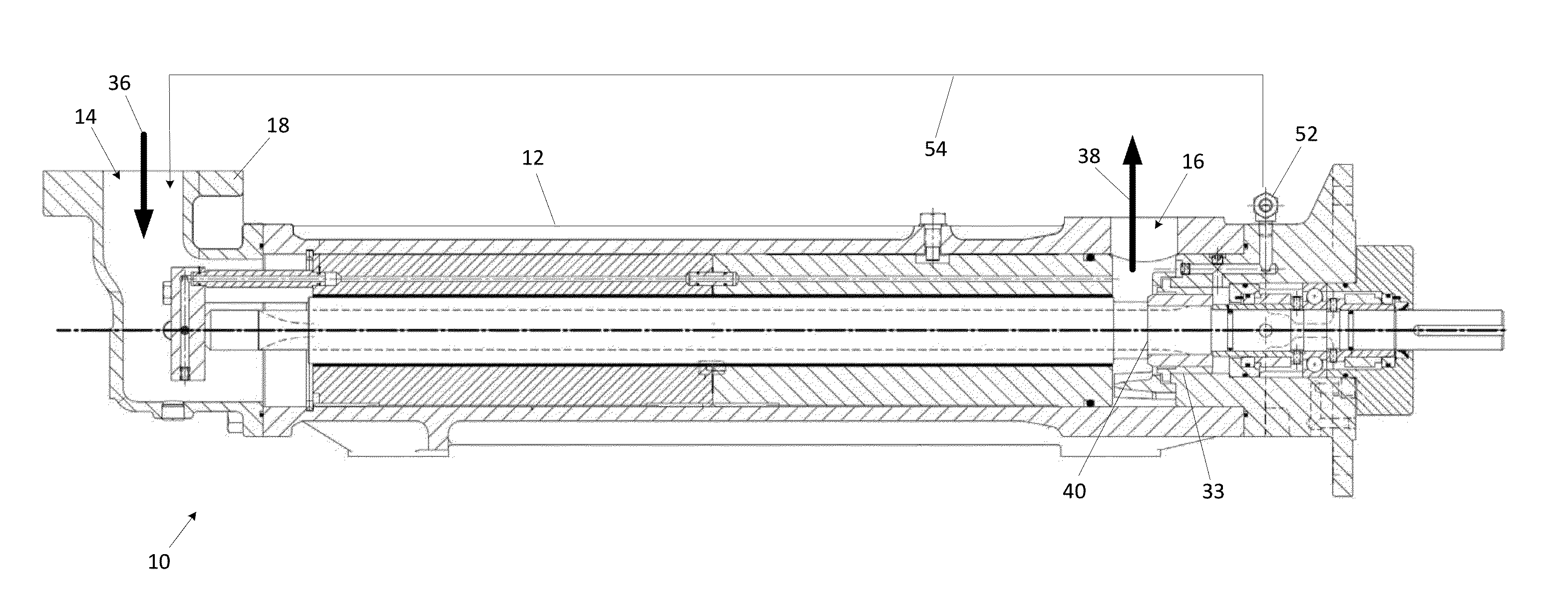
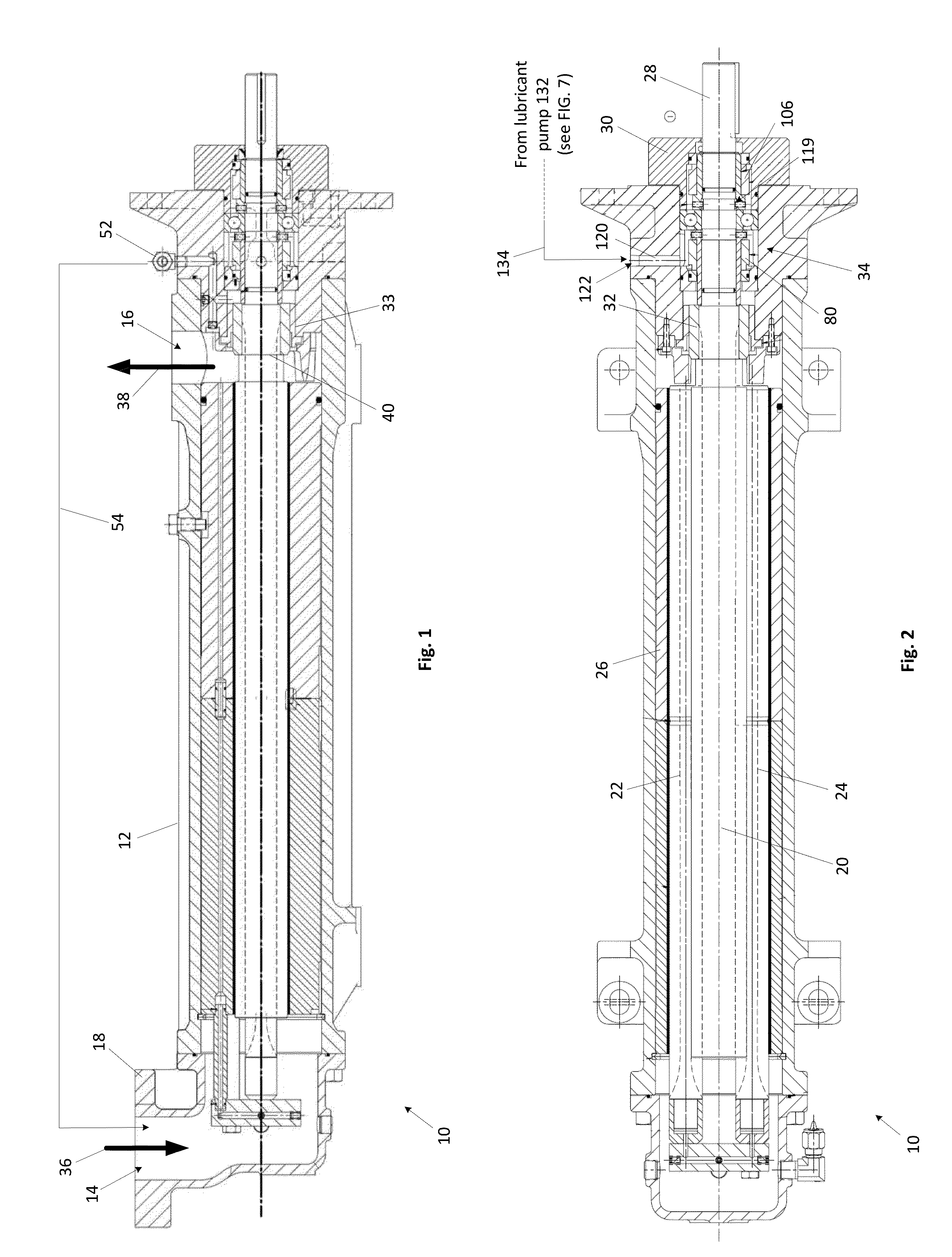
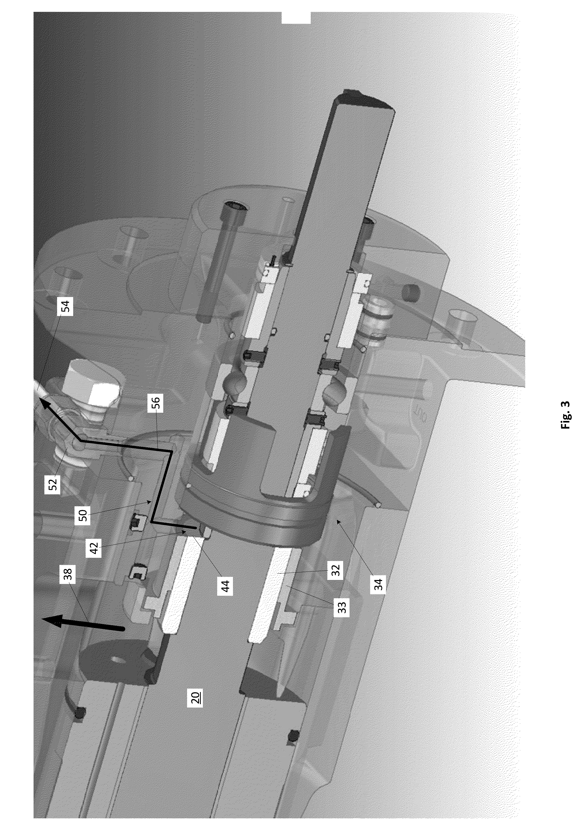
[0019]FIG. 1 shows a sectional side view of an exemplary pump with a double mechanical seal arrangement (hereinafter referred to as “the pump 10”) in accordance with an embodiment of the present disclosure. For the sake of convenience and clarity, terms such as “top,”“bottom,”“lateral,”“longitudinal,”“up,”“down,”“upstream,”“downstream,”“inwardly,” and “outwardly” will be used herein to describe the relative placement and orientation of the...


PUM


Abstract

A fluid pump configured to prevent contact between volatile fluids and a ball bearing of the pump while providing the ball bearing with adequate lubrication. The fluid pump includes a pump casing having a fluid inlet and a fluid outlet, and a rotor set disposed within the pump casing for conveying fluid from the fluid inlet to the fluid outlet. The fluid pump further includes a recirculation chamber located adjacent the fluid outlet for collecting leaked fluid. The leaked fluid may be conveyed from the recirculation chamber back to the fluid inlet due to a pressure differential therebetween. The fluid pump may further include first and second seals that surround a drive shaft of the rotor, the first and second fluid seals defining a lubricant compartment therebetween that houses a ball bearing of the pump and that is filled with a continuously circulated, nonvolatile lubricant.

Description

FIELD OF THE DISCLOSURE[0001]Embodiments of the present invention relate generally to the field of fluid pumps, and more particularly to a fluid pump having a double mechanical seal arrangement with an embedded ball bearing for pumping volatile fluids.BACKGROUND OF THE DISCLOSURE[0002]A conventional screw pump typically includes an elongated pump casing having a fluid inlet located adjacent a first longitudinal end thereof and a fluid outlet located adjacent a second longitudinal end thereof. A rotatably driven screw (commonly referred to as a “power rotor”) and two or more intermeshing idler rotors extend through the pump casing and operate to drive fluid from the fluid inlet to the fluid outlet. An end of the power rotor nearest the fluid outlet often extends through a ball bearing that supports the power rotor and allows the power rotor to rotate freely about its axis with minimal frictional resistance. The power rotor typically also extends through a mechanical seal that separat...

Claims


Application Information

Patent Timeline
Patent Type & Authority Applications(United States)
IPC IPC(8): F04C18/10
CPCF04C18/10F04C15/0038F04C2/165F04C15/0088F04C15/0092F04C15/06F04C18/16F04C29/02F04C29/025F04C2230/60F04C2240/50F04C2270/46
Inventor JABLONSKI, JOSEPHGREENE, COLETTE DOLL
Owner CIRCOR PUMPS NORTH AMERICA LLC
Learn More