
Component Connector for Connecting Cylindrical Components

a technology of connecting components and connectors, which is applied in the direction of fluid pressure sealing joints, sleeves/socket joints, pipe joints, etc., can solve the problems of difficult detachment of cured adhesives on the end faces, damage to connected components, and difficult reopening of connections, etc., to achieve rapid and simple fixing, easy assembly, and easy insertion

Active Publication Date: 2015-06-11
ARNOLD JAGER HLDG GMBH
View PDF1 Cites 0 Cited by
  • Summary
  • Abstract
  • Description
  • Claims
  • Application Information

AI Technical Summary

Benefits of technology

The invention is a component connector for pipes that allows for a quick and reliable connection with minimal components. It has a unique surface profiling that prevents the clamping ring from rotating in the opposite direction, ensuring a secure and effective seal. The connector allows for easy assembly and disassembly with various component shapes, eliminating the need for adhesives or heat treatment. The components are reusable, reducing costs and minimizing effort. The connector protects the sealing portion from external damage, ensuring reliable fixing and sealing.

Problems solved by technology

In these approaches, it is disadvantageous that the connections are very difficult to reopen.
On the one hand, stretched casings made of thermoplastic or thermoelastic plastic, for example, are removable only with effort, and on the other hand, a cured adhesive on the end faces is not easy to detach without also damaging the connected components.
Furthermore, the casing is easily accessible from the outside, and may thus be damaged not only in the stretched state, but also during attachment.
Damage to the casings has an effect primarily on the seal-tightness and the reliability of the connection.
As a result, leakage of a liquid or escape of a gas as well as shifting of the pipes are not reliably preventable.
Therefore, rapid opening and closing of the component connection as well as frequent use of the same component connector or component cannot be ensured.

Method used


Image

  • Component Connector for Connecting Cylindrical Components
  • Component Connector for Connecting Cylindrical Components
  • Component Connector for Connecting Cylindrical Components

Examples


Embodiment Construction

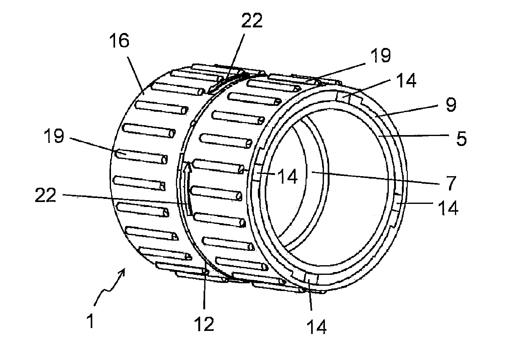
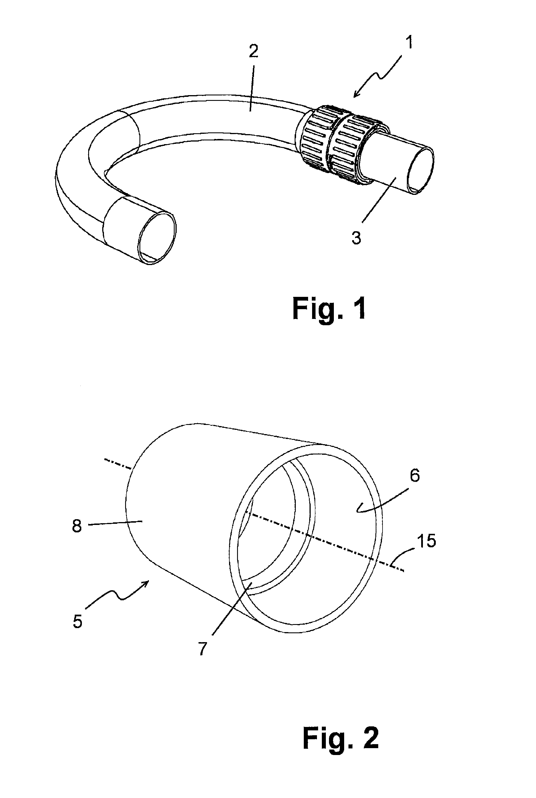
[0038]FIG. 1 shows a perspective view of a component connector 1 which connects two pipes 2 and 3. Individual components of the component connector 1 are explained in greater detail below with reference to FIGS. 2 through 7.

[0039]FIG. 2 shows an elastic sleeve 5 which forms an inner part of the component connector 1. The elastic sleeve 5 has a hollow cylindrical shape, in the installed state an inner wall 6 of the sleeve 5 resting on the pipes 2, 3 to be connected. The elastic sleeve 5 is preferably made of a plastic or an elastomer, by means of which the elastic sleeve 5 is deformable.

[0040]A circumferential web 7 which is situated approximately centrally is provided on the inner wall 6 of the elastic sleeve 5. The height of the web 7 corresponds approximately to the thickness of a wall of the pipes 2, 3 to be connected, so that the flow of a fluid which is conducted in the pipes 2, 3 is not hindered by the web 7. The web 7 may be a part of the elastic sleeve 5, but may also be adh...


PUM


Abstract

Component connector for connecting cylindrical components includes an elastic sleeve which surrounds the components, the elastic sleeve can be braced, a radially deformable fixing sleeve is provided which encloses elastic sleeve. Elastic sleeve is braced via radial deformation of fixing sleeve in a perpendicular direction to a longitudinal axis of fixing sleeve, and at least one clamping ring is provided for radially deforming fixing sleeve. Fixing sleeve has a profiled outer wall and clamping ring has an oppositely profiled inner wall so clamping ring can be pushed concentrically onto fixing sleeve in an accurately fitting manner, during a relative rotation of clamping ring, placed in an accurately fitting manner, in a closing direction, the fixing sleeve can be deformed radially inwardly by the surface profiling; and, during a relative rotation of clamping ring counter to the closing direction, the surface profiling prevents any rotation.

Description

CROSS REFERENCE TO RELATED APPLICATIONS[0001]This application is a continuation of application No. PCT / DE2013 / 100057, filed 14 Feb. 2013, which claims the priority of German Application No. DE 10 2012 003 817.8, filed 25 Feb. 2012, and each of which is incorporated herein by reference.FIELD OF THE INVENTION[0002]The invention relates to a component connector for connecting cylindrical components. More particularly, the invention relates to a component connector for connecting cylindrical components, in particular pipes, and even more particularly, pipes for carrying fluids, such as gases or liquids.BACKGROUND OF THE INVENTION[0003]Component connectors or pipe connectors are already known from the prior art. They are used to fixedly connect two pipes in which a gas or a liquid, for example, may be conducted, so that the gas or the liquid may flow through the connected pipes.[0004]To this end, an arrangement for producing extended channels is provided in Utility Model DE 299 08 172 U1...

Claims


Application Information

Patent Timeline
Patent Type & Authority Applications(United States)
IPC IPC(8): F16L21/00F16L21/08F16L21/06
CPCF16L21/007F16L21/08F16L21/06F16L37/101F16L49/06
Inventor BACHMANN, HANS-PETERBABEL, STEFAN
Owner ARNOLD JAGER HLDG GMBH
Learn More