Air passage device for admitting purified air into an interior of a control cabinet

a technology for air passage and control cabinet, which is applied in the direction of electrical equipment, cooling/ventilation/heating modifications, and gaseous coolants, etc., can solve the problems of dust and aerosol pollution, and achieve the effects of avoiding frequent replacement of filter elements, increasing cost, and avoiding loss of pressur

Inactive Publication Date: 2015-05-28
PFANNENBERG GMBH
View PDF5 Cites 7 Cited by
  • Summary
  • Abstract
  • Description
  • Claims
  • Application Information

AI Technical Summary

Benefits of technology

The patent text describes an air passage device that uses a centrifugal separator as a first air purifying means. This device helps to cool the interior of a computer housing or control cabinet by introducing purified air. The centrifugal separator collects dirt particles over a longer period of time, which means it requires less frequent replacement. The device also avoids pressure losses or reductions, which can occur when using filters. A filter, such as a filter mat, can be used as a second air purifying means, and it requires less frequent replacement compared to devices without a first air purifying means. The second air outlet opening is preferably located on the top of the device, which reduces the negative effects of the warm used air discharged from the device. Overall, this air passage device is cost-effective, low-maintenance, and provides effective air purification without the need for high-maintenance and expensive cooling systems.

Problems solved by technology

In particular this includes pollution by dust and aerosols, air laden with oil or emulsion-containing air.

Method used


Image

  • Air passage device for admitting purified air into an interior of a control cabinet
  • Air passage device for admitting purified air into an interior of a control cabinet
  • Air passage device for admitting purified air into an interior of a control cabinet

Examples


Embodiment Construction

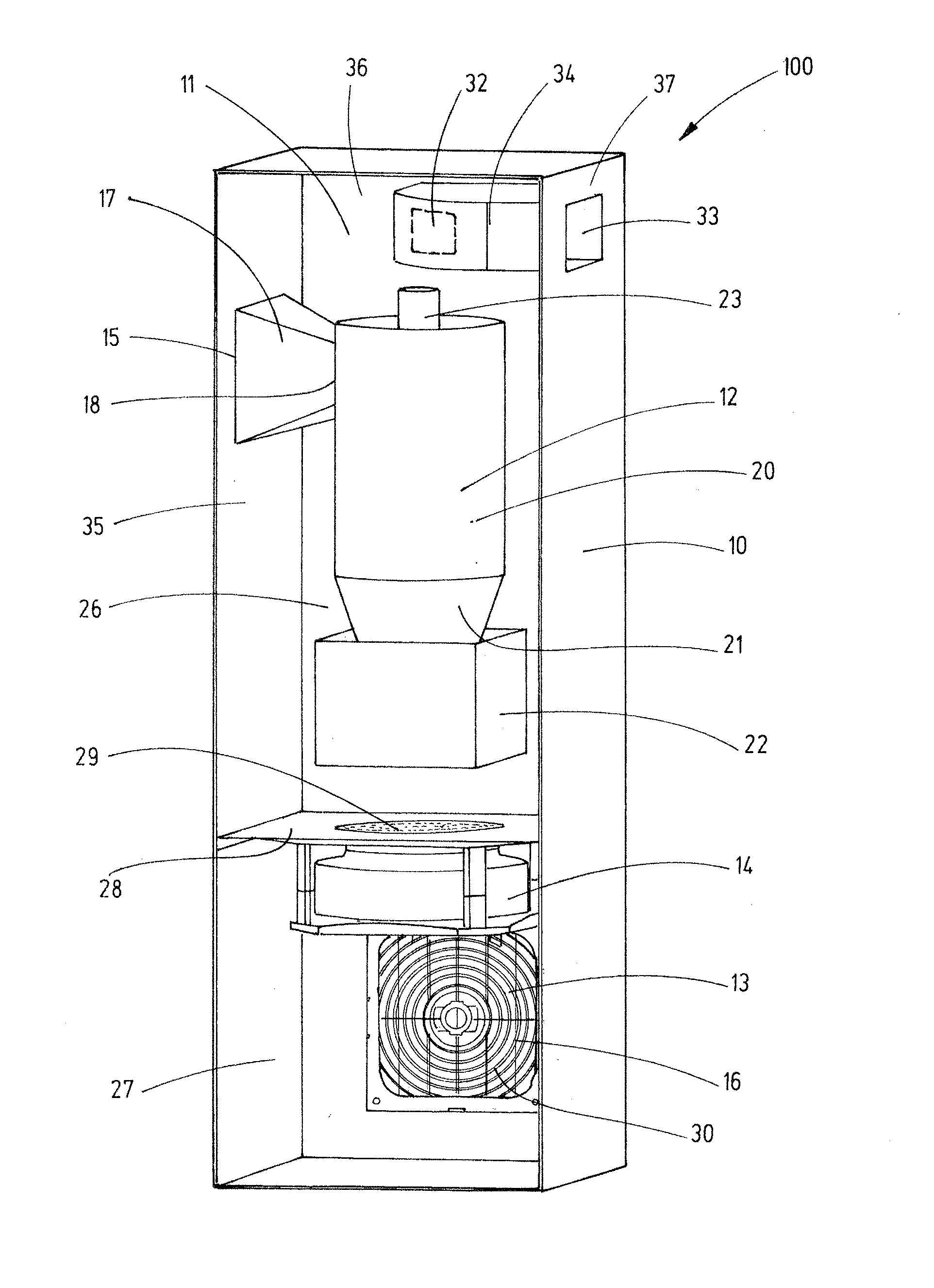
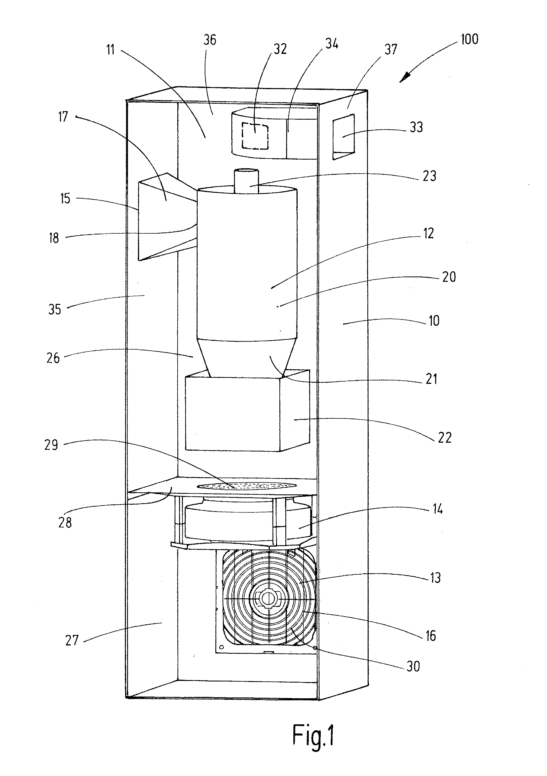
[0060]FIG. 1 shows an air passage device 100 for arranging in a control cabinet 200. The air passage device 100 of FIG. 1 is shown to be open on one side in order to be able to see the components arranged within. It means that the fourth side wall 38 of the air passage device 100 is not shown in FIG. 1.

[0061]The air passage device 100 comprises a housing 100 with four side walls 35, 36, 37, 38 as well as a topside and an underside. In the upper area of the air passage device 100 a first air inlet opening 15 is arranged in the first side wall 35 of the air passage device 100. The first air inlet opening 15 is connected via an entry duct 17 with the inlet opening 18 of the first air purifying means 12. The entry duct 17 from the first air purifying means 12 to the inlet opening 18 is shaped as a funnel. The first air inlet opening 15 of the air passage device 100 is thus larger than the inlet opening 18 of the first air purifying means 12.

[0062]The interior 11 of the air passage devic...


PUM


Abstract

In order to arrange an air passage device for the admission and purification of air, in particular ambient air, into the interior of a control cabinet or computer housing in such a way that the device can be used also in an environment which is subject to an increased degree of pollution, a first purifying includes a centrifugal separator.

Description

CROSS-REFERENCE TO RELATED APPLICATIONS[0001]This application is entitled to the benefit of and incorporates by reference essential subject matter disclosed in German Patent Application No. 102013112977.3 filed on Nov. 25, 2013.FIELD OF THE INVENTION[0002]The invention relates to an air passage device for admitting air, in particular ambient air, into an interior of a control cabinet or a computer housing, in particular a server housing, wherein the air, before being admitted into the interior of the control cabinet or the computer housing, is purified.[0003]Further the invention relates to a control cabinet with an air passage device for admitting the purified air into its interior.BACKGROUND OF THE INVENTION[0004]Control cabinets comprise electric and / or electronic components of a process plant, a machine or a production facility, wherein these components are normally not arranged directly in the machine.[0005]The electric and / or electronic components arranged in the control cabin...

Claims


Application Information

Patent Timeline
Patent Type & Authority Applications(United States)
IPC IPC(8): H05K7/20
CPCH05K7/20009H05K7/20181H05K7/20572
Inventor PFANNENBERG, ANDREASSTARP, PETER
Owner PFANNENBERG GMBH
Why Eureka
Try Eureka